The video system plays a big role in a computer, especially when working with graphics systems and in games. It performs special calculations in order to transfer the result of such calculations to the monitor screen for visualization of the image. Typically consists of a graphics processor, video controller, video memory, digital-to-analog converter, video ROM, and may have its own cooling system. If the user works with a text editor, music, Internet or similar programs, then the fast operation of the video system is not so important and standard video systems are quite sufficient for such programs. Therefore, in this chapter we will look at the features of image output and some other issues.
Each screen is made up of small dots called pixels. Under the concept screen resolution refers to the number of available pixels horizontally and vertically. For example, 800x600 pixels, that is, 800 horizontal columns and 600 vertical rows. Sometimes the term “resolution” refers to the number of dots per inch, for example, 80 dots. But that rarely happens. All of the above applies not only to cathode-ray displays, but also to other types, for example, liquid crystal displays, which also have pixels and similar characteristics, although the principle of displaying information on the screen is different. The number of pixels on the screen and the color depth are determined by the size of the memory for storing the screen image.
What if the screen resolution is larger or smaller than the output? In this case, each point will be represented in some average value. If the screen resolution is lower than the output resolution, the picture will be blurry because some information will not be output. If it is more, then a normal picture is often obtained, since the average value is displayed, with the exception of liquid crystal displays, in which the picture is normal only if the screen resolution and the displayed image correspond, a multiple of an integer number of times.
Different displays may use different flower models. The most common is RGB(Red, Green, Blue - red, green, blue). Moreover, each shade of color is determined by three numbers, where the first indicates the brightness of red, the second - green, and the third - blue. For example, (0,0,255) means pure blue. But there may be other combinations based on other colors, for example, CMY(Cyan, Magenta, Yellow - blue, cherry, yellow) or CMYB(Cyan, Magenta, Yellow, Black - blue, cherry, yellow, black), where in addition to the three primary colors an additional black color is used. This is especially important when using inkjet printers, since when outputting black and white using a combination of primary colors, it is difficult to achieve normal shades and often produces only dark blue or off-white color. Therefore, printers for high-quality printing (so-called photo printers) use their own ink for black. This is especially convenient when printing only black and white images, since black ink is usually cheaper than color ink. There is also a model H.S.B.(Hue, Saturation, Brightness - hue, saturation, brightness), which is used to form a television image.
On a CRT (cathode ray tube) screen, when an electron beam passes through it, the colored areas receive pulses that store the color, which disappears over time. Therefore, it is important to update the screen on time. If the charge drains quickly, the screen flickers. Liquid crystal screens use a different principle, since the charge does not drain onto them, but operates for a certain time, so it must be replaced on time. Such screens display a static image better, without quickly changing the image.
First displays MDA, Monochrome Display Adapter was introduced by IBM in 1981 and could only display text information in monochrome (one-color) form, and there were 25 rows by 80 columns for displaying characters. Information for each position required two bytes, one of them contained the character code, the second byte determined in what form it should be displayed (underlining, blinking, brightness). Thus, a total of 4,000 bytes were required to store information about the screen and all information was placed in RAM. Later an adapter appeared C.G.A., which allowed the display of graphic information and each pixel could contain one of four colors.
The adapters have been modified, but the display principle remains the same, and now text and graphic information can be displayed on the screen. Modern displays have increased the number of pixels (rows and columns) as well as the number of colors it can display. Color depth is a parameter that determines the number of colors that can be displayed by one pixel. The more colors, the larger the memory needed to store the image. For example, four bits can define 2 4 =16 colors, eight bits can define 256 colors, and so on. The most commonly used are 2, 4, 6, 16, 24, 32 bits per pixel.
The first computers had a video buffer in RAM, information from which was displayed on the screen. For the graphic image, all calculations were performed by the central processor, but later, in order to unload it, they installed GPU(also called graphic accelerator, graphics accelerator etc.) to which the central processor sends general instructions for image manipulation.
The monitor has the ability to work in different video modes, each of which determines the type of information displayed on the screen (character or graphic), the number of image elements (rows, columns of characters/pixels), image color depth (number of bits per color), and so on.
According to how the image is displayed, the programs are called: raster or vector, 2D (two-dimensional) or 3D (three-dimensional). Raster images are like a matrix, where each point has its own color values and saturation. The vector format involves drawing objects in the form of contours, the coordinates of which create the possibility of displaying it. A vector program allows you to create layers of images, that is, you can move an object (for example, an image of a tree) to another place in the picture, and what was behind the tree will move to the foreground, that is, appear in the picture.
Three-dimensional image. When creating a three-dimensional image, the calculation is divided into several stages. At the first stage, a frame of objects is created. At the second stage, the surface is divided into elementary objects (triangles, rectangles, etc.), then the surfaces are colored taking into account the reflection and absorption of light. Then a projection from a three-dimensional image onto a plane occurs with a change of vertices, in order to determine which vertex will be in front and which will be off the screen (Z buffer), they are sorted, converted into integer values with the removal of unnecessary vertices. After this, textures are applied to the object, as if a pattern is applied to a surface, for example, the structure of wood, plastic, tiles, etc., then transparency analysis is performed and defects are removed. In addition, non-standard procedures can be added, for example, creating the effect of fog, snow, etc. The first stages of processing work with vector elements, and then, with a two-dimensional representation, they move on to raster processing or rendering. All these operations can be performed by the central processor, but if you have a good video card, part of the calculations is taken over by the video processor.
At each stage, a large number of operations are performed, especially when applying textures. Working with an image has many types of processing, for example, antialiasing, alpha shifting, MIP texturing, etc.
In most video cards, video memory is used double buffering, in which first one frame is output and the second is processed, then the second is output, the first is processed, etc. At the same time, the video accelerator is characterized by the type of supported libraries, shading speed, set of implemented functions, maximum number of processed textures, etc.
There is currently no single software interface for 3D imaging as there are many different types of software available.
Among the most famous are the following libraries with template routines:
OpenGL(Open Graphics Language) was created by Silicon Graphics me and is more designed for scientific tasks, CAD, but is also used in games. This library is included in Windows and objects in this format can be moved around the screen. Works with animation, two- and three-dimensional images, visual effects, sound.
API quick draw 3D– developed by Microsoft, focused on simple products for the masses and is often used in games.
Glide- developed by 3Dfx using the Voodoo chipset. It has a more complex interface, but is faster.
Direct X- developed for Windows 9x and includes: Direct Draw - for quickly displaying images from RAM on the screen, as well as accelerating two-dimensional constructions; is a video card manager; Direct 3D - a set of graphics acceleration for three-dimensional objects, allows you to track irregularities, create atmospheric effects, perform Z-buffering and perspective-taking; Direct Input - provides work with joysticks, helmets, etc.; Direct Sound - allows you to work with sound; Direct Sound 3D - allows you to work with sound in three-dimensional space; Direct Play - allows interaction between different players; Direct Music - works with Midi; synthesizer programs; Direct Animation – works with animation (cartoons) and supports vector graphics, three-dimensional graphics, sound, etc.; Direct Transform - creating visual effects such as image transformation, ripples, etc.
Using a video card can be implemented following modes:
Drawing of graphic primitives, in which an object consists of small elements, triangles, rectangles, etc. For this purpose, a processor on a video card is often used, the actions of which are authorized by the central processor;
Support for on-screen windows. If the computer has several running windows, then each window is allocated a buffer in which the program runs, and the graphics card combines these areas into one and displays them on the screen;
Transferring images (windows, shortcuts, window scrolling) can be implemented using hardware, without using a central processor, in particular, creating a mouse cursor on the screen;
Unpacking a video image, for example, using the JPEG2 algorithm and transferring the image from one mode to another;
Scaling raster images. This can be simple magnification, which introduces jaggies into the slanted lines, or interpolation, where intermediate data is calculated and the jaggies disappear.
Additional features of video cards
There are the following additional options for video cards:
Frame grabbing- image capture, in which one frame can be snatched from a video data stream and stored in digitized form in memory. In this case, you should pay attention to the resolution, number of supported colors, type of supported graphic files, data compression method;
Hard Disk Editing- non-linear editing. The ability to edit frames using special software and effects that can be applied during editing. Linear installation means that when searching for what you need, rewinding is used, as it happens when working with a video cassette. With non-linear editing, the data is on the hard drive and any frame can be accessed;
Live video in a Windows - live video in Windows system. Ability to view videos in a Windows system window. It is desirable to be able to operate the video card without the participation of a central processor;
Movie grabbing- video digitization. In this case, you need to pay attention to the resolution, the number of frames per second, the number of colors, the presence of an accelerator, compatibility with different formats;
Tape Editing - linear signal. Ability to edit images on video tape. One must consider the type of standards the film's image is subject to;
TV tuner- TV tuner. A device that extracts the signal from a television antenna. The main characteristics are the set of television channels that can be received, supported standards;
Video decoding- video decoding. The ability to edit information recorded on an optical disc, compression according to the MPEG1 standard, which can be done according to two standards: White book (white book) and Green book (green book).
To display three-dimensional images on a regular screen, the same principles are used that are inherent in the representation of an image by the human eye, namely the perception of reduced objects as distant, if one object obscures another, then it is closer, as well as the principles of constructing chiaroscuro. However, there are devices that allow you to display an image for each eye separately, which creates a three-dimensional effect.
If there is no driver for the video adapter, then, since there is no specific standard for the SVGA mode, you can use the standard driver in Windows 9x, although it does not fully support the display capabilities in all cases.
The description of the video card may indicate that it has a 128-bit bus, or may contain other numeric values for this parameter. If the video card is connected to the PCI bus, then it is 32-bit. In this case, 128-bit refers to the internal bus from the video processor to the video memory. Naturally, the higher the bit depth, the more productive the video card.
The monitor can also work with video data, this direction is currently actively developing. This is due to the fact that previously its development was hampered by the availability of low-power hardware. It was possible to display only part of the image on the screen, and even then, it did not always support the normal frame rate; the output was produced with delays. The development of processors and video cards makes it possible today to produce full-screen output with a good frame rate, and the capacity of modern hard drives and data compression make it possible to store a lot of video information.
You can display videos on your computer screen, but not all computers can support them at a good level. If the image is displayed on the entire screen without skipping a frame, then they speak of a full-screen, full-fledged video. If the computer does not allow this, then you can display the image in a small window on the screen or, skipping some frames, display a specific one, for example, the second, fourth, etc. frames.
There are special video cards for working with video, which are called grabbers (from the word grab - to capture), video blasters, video input devices and allow you to: receive an analog signal (from a video monitor, television tuner and other devices); display the image in a window on the display screen; capture a frame and digitize it, that is, convert data from analog to digital form; convert digitized information into graphic format and store it on your hard drive.
Main video card components are the following elements:
A video decoder, which receives an analog signal, digitizes it and transmits it to the video controller;
Video controller. Receives data from the video decoder, converts it and transfers it to buffer memory via the system bus for the central processor for further recording to the hard drive, and then transfers it to a digital-to-analog converter;
Memory, video buffer, where intermediate data is stored;
A digital-to-analog converter that receives data from a video controller or video buffer and sends it to the display screen, converting it from digital to analog form.
TV video signal is a YUV signal consisting of: a brightness signal, UV color carriers, sync pulses. There are special formulas that allow you to move from one system to another (Y=0.299R+0.5876G+0.114B U=R-Y V=B-Y).
In format VHS 240-260 television lines are used horizontally on the screen, in S-VHS - 400, when using professional equipment - 500 lines, in practice there may be more for some scientific measurements. This format is also used in VCRs.
TV can work in the following formats:
PAL(Phase Alternation Line - a line with a changing phase) was developed in Germany in 1963 by Telefunken and is used in most countries of Western Europe, as well as in some countries in Asia and Africa. Many video cameras work in this system, and videotapes are often recorded in this way.
NTSC(National Television System Committee - national committee on television systems, USA). It is distributed in the USA, North and South America, as well as in Japan, South Korea, Taiwan and a number of other countries. NTSC 3.5 - used in the USA, Japan and has a color carrier of 3.579 MHz. NTSC 4.4 is a system used in the UK and the Middle East, with a carrier frequency of 4.4336 MHz.
SECAM(Sequential couleur avec memoire - sequential transmission with filling, Secam). Developed in France, adopted in 1967, used in Russia and the CIS countries, in many former socialist countries, in some countries of Africa and Asia.
Due to the fact that different systems use different numbers of lines, for example, after switching from NTSC to PAL, there will be dark bars at the top and bottom of the screen. The same thing happens with watching American films on our TV, with special methods either adding dark lines at the bottom or top of the screen, or part of the image is cut out of the frame, and the side fragments are not reproduced, but the frame occupies the entire screen.
HDTV(High Definition TeleVision) represents improved quality standards for the transmission of digital television signals. The signal is transmitted in compressed form, compressed using MPEG-2 and MPEG-4/AVC formats. To transmit data via satellite television, DVB -S, DVB -S 2 technologies are used, for cable television - DVB -C, for terrestrial television - DVB -T, DVT2. Transmission over short distances occurs without compression via HDMI, DVI-D cables. There are three standard formats:
720p for frames sized 1280x720 with a frequency of 50, 60 frames per second and progressive scanning, aspect ratio 16:9 (in Russia it is called high-definition television);
1080i for frames of size 1920x1089, with a frequency of 25, 30 frames per second and interlaced scanning, aspect ratio 16:9;
1080p for frames measuring 1920x1089, with a frequency of 24, 25, 30 frames per second and progressive scan, aspect ratio 16:9;
1080p50 for frames measuring 1920x1089, at 50 frames per secondand progressive scanning, aspect ratio 16:9;
1080p60 for frames measuring 1920x1089, at 60 frames per secondand progressive scanning, aspect ratio 16:9.
The standard has image copy protection using AACS and HDCP technologies.
AACS(Advanced Access Content System) was created in 2005 and is designed to protect DVD HD and Blu-ray discs from copying. However, the key was soon decrypted and posted on the Internet. In addition, there are programs on the Internet that support copying encrypted disks.
HDCP(English: High-bandwidth Digital Content Protection - protection of digital content with high bandwidth) - allows you to protect the video signal when transmitted via HDMI, DisplayPort cables. It is not mandatory, but if present, it must be on two devices: the receiving and the sending. Used in HD DVD And Blu-Ray players. The playback device must also support this standard. In 2004, it was approved by law in the USA.
Due to the fact that one frame takes up to 1 megabyte, 25 frames require memory up to 25 megabytes, which corresponds to 1 second of full-screen video. To deal with this problem, usually data is compressed, for which there are special algorithms. The Gif and Pcx formats compress data without loss of information or quality. The Jpeg format may lose some data when compressed. Naturally, compression (compression) and decompression require time or the presence of a graphics adapter to relieve the central processor.
One of the most common is the JPEG method, which can be performed using programs that require high CPU speed, or using video cards, which allows you to offload the central processor and perform calculations autonomously. In addition to it, there are ways to compress information: MPEG-1, (White Book - a white book, used for Video CDs, and Green Book - a green book for CD-I disks), M-JPEG, Intel Indeo Video and others. At the same time, some of them compress audio data, while others do not.
Compression performs two tasks: data compression and data decryption. Data compression is not time-critical, that is, data can be compressed not in real time, but over a longer period of time. At the same time, decryption is time-critical, since if the data is not decrypted in time, the image on the display screen will be displayed intermittently.
There are many types algorithms for information compression.
VideoI AndIndeo. In this algorithm, the image is decomposed into simple geometric elements and recorded in vector form. At the same time, the preservation of information about brightness is implemented with a decrease in the amount of information about color (loss of some data), since the human eye perceives brightness well and colors worse.
JPEG– compresses each frame, while breaking it into blocks, which are compressed.
MPEG– based on the transmission of changes in a sequence of frames. Due to the fact that each subsequent frame has few differences from the previous one, it is possible to remember one frame, and only remember the changes in the next ones. To do this, MPEG uses three types of frames: key (I frame), that is, the main one, on the basis of which other frames will be built, dependent (P frame), that is, having influence on other frames, and two-way (B frame), which depends not only from the previous, but also from the next frame. In the latter case, digitization takes quite a long time; a complex analysis of both previous and next frames is performed. However, recovery is fast, which is why MPEG devices have become widespread. MPEG-1 is used in video-CD.
A new standard was then developed MPEG-2, which began to be used in DVD discs. In this case, the image is displayed with a resolution of 352x240 pixels. To remember information about the entire screen, new lines are added using special methods. Used for digital television, satellite television and DVD.
MPEG -3 began to be developed for HDTV, but it turned out that using MPEG-2 was sufficient.
MPEG -4 compresses video and audio data, used for television, HD DVD, Blu-Ray discs.
In home computers, the DV (Digital Video) format is more often used, which is based on compression of each frame and allows you to reduce the file size by about five times, contains an error correction scheme, that is, if a certain percentage of data is lost, it can be restored. Compression and decryption occurs quite quickly. There are video cameras that work using this method. Using the IEEE1394 bus, data from 25 to 50 Mb/s can be transmitted over a 4.5-meter cable through a special interface in the computer. The JLIP protocol allows video devices connected to a computer to operate. At the same time, when capturing a frame, it does not write it to disk, but only information about the location on the tape, which can then be worked with.
In order to work with different formats there are video codecs(algorithms or programs that determine how to work with the video format). Audio data has its own audio codecs. If video or audio does not play in the player, then you need to install a program, for example, K-Lite Codec Pack.
There are quite a large number of video and audio data formats that include a video compression method or algorithm - H .261, H 262, H 263, H 264, AVI, AVS, Bink, DivX, Indeo, Mjpeg, MOV, RealVideo, Theora , VC, VP 6, VP 7, VP 8, WMV, SIF 1, x 264, XviD, audio – MPEG, OGG, GSM-FR, AMR, G.723.1, G.729, iLBS, mp 3 and others.
Since some data is lost when digitizing frames, deterioration may occur during display. This is best seen when capturing a frame and viewing it; imperfections are best seen when printing the image onto a sheet of paper using a printer. There may be the following flaws: A stationary background appears to be moving; patterns appearing on the screen; the appearance of a rainbow on large single-color objects; the appearance of squares on the screen that appear due to the inaccuracy of the conversion in the DCT format; the image is as if you are looking through a dirty window glass, through a haze; loss of small details, flickering may occur that actually did not exist; a trace of movement is visible behind a fast-moving object, for example, if you quickly wave your hand, then a trace is visible behind it, just like behind another fast-moving object (for example, a car); contrast enhancement.
In addition to the above, there are other video compression algorithms and standards. Standard devices with additional capabilities are also beginning to be produced for working with video. For example, there is a printer that can output an image frame from a TV or VCR without connecting to a computer.
May apply when viewing special glasses for viewing a three-dimensional image (3D glasses), the operating principle of which may be different. It could be glasses with active shutter, which alternately do not allow one eye to see the screen, while when closing the image for the right eye, the left one sees the picture on the screen intended for it, then the image for the left eye closes (the eyes themselves do not close), the image for the right eye opens, and appears on the screen the picture corresponding to the right eye, etc. There may be glasses that have two screens, one for the left eye and one for the right. In another version, the glasses transmit polarized light, with one polarization direction for the left and another for the right, and both images are displayed on the screen, with each eye seeing its own image. There are helmets in which a different image is presented to each eye. Its main characteristics are resolution and the number of colors displayed. In addition, translucent glasses are produced, which, in addition to the image on the screen, allow you to see the surrounding environment.
Interesting technology is being developed that allows transmit the image directly to the eye user, onto his retina. This technology is called SPS Display, in its full version Scanning Photonic System Display, which translates as “display based on photon capture.” With this scheme, three LEDs - red, blue and green - shine on a special MEMS (Micro-Electro-Mechanical System Chip) chip. This microcircuit controls the movement of the mirror, the light from which, when reflected, enters the retina of the user's eye. The mirror is controlled in such a way that the beam of light performs a sweep on the retina of the eye, similar to that of a conventional CRT-tube television.
There are also special monitors for working with three-dimensional images. They receive polarized light, using even lines for one eye and odd lines for the other. By wearing special polarized glasses, we get a stereo effect. There may be other types of monitors that work both with and without glasses, but they are quite expensive and have not yet found widespread use.
Please note that monitors are produced with built-in TV tuners, allowing you to watch TV shows from the display screen. Such devices have a remote control to change channels and make the necessary settings. However, it is still not possible to perform two functions well in one device, since LCD matrices have significant “response” times, that is, the time it takes for the picture to change.
Special monitors are also produced that combine the function of displaying visual information With input using a wireless pen by pressing it on the monitor screen, so-called graphics tablets. The screen coating can typically detect up to 512 levels of pressure from the pen, which does not require power.
Helmet may have sensors for rotation and movement of the head, and the computer simulates an image corresponding to this position. In addition, it has built-in speakers and a microphone. Helmets can also be equipped with additional sensors, including gloves, that analyze the movement of each finger. There are special suits that have sensors all over the body, these are often used for making cartoons. To do this, a three-dimensional model of an object is created on a computer, for example, an animal, a person is put on a suit with sensors all over his body, and when he moves, the sensors record the trajectories of his movement. These coordinates are transmitted to the computer, which builds a model from them at certain points in time.
Sensors can be of three types: magnetic (have inductive coils that create electromagnetic fields, the receiver registers changes in this field), ultrasonic (sensors create ultrasonic vibrations) and inertial (have a gyroscope, also used on ships and airplanes).
In Internet there is its own version of 3D modeling, which is described in a special language - VRML. To view a 3D image, you need to connect the VRML module to the browser, after which you can view the transferred 3D image from different positions.
Three industries have made major contributions to the development of 3D image presentation: computer games, exercise equipment, and television videos. In addition, they are used in architectural programs where a building can be viewed from both the outside and inside from any point; in educational ones, where, for example, you can see in detail the old city, its life, the location of houses, and so on.
If 16 or 256 colors are displayed on the screen, you can change their shades using a special Color lookup table, in which each color has its own interpretation. When a signal is received from the computer to output a certain color, for example, 1 (blue), this table is accessed, where the values for this color are taken in RGB form, 6 digits per primary color. The standard value for example for blue is (0,0,42), where there are three values, one for each color: red, green and blue. When changing the palette, you can vary the shades of primary colors. This principle is used in the Gif format, which contains not only a description of the image, but also a color palette, which allows, when using 256 colors, to obtain images close to photographic quality.
When you print a color image on a printer, it looks slightly different than on the screen. If you want to achieve color matching, you need to set your monitor to output colors similarly to your printer. To do this, use the driver program that comes with the video card or printer driver. This problem is called color correction. Color printers may come with a special file called a printer settings file. With its help you can try to solve this problem. In Windows 98, it is possible to manage color using the CMM (Color Management Consortium) module. Printers that have the Windows 98 logo usually support this mode. To set this mode you need to use: Start → Settings → Control Panel → Display → Settings → Advanced → Color Management.
Despite the fact that a computer monitor has the ability to display images with a higher resolution than TV, which displays no more than 500x400 pixels, it often seems that the image on the TV is better than on the computer monitor. There are several reasons for this. Firstly, the TV cannot display small characters as well as the display; they will be blurry. Secondly, a person watches TV at a greater distance than at a working monitor. Try to watch TV at a distance of 30-40 cm from the screen, and you will see a less clear picture and, in addition, it is hard on the eyes. Thirdly, the TV is designed more for displaying moving images, when the human eye catches the movement and does not pay much attention to the background. In addition, the programs shown on TV are made by professionals, highly educated cameramen, directors and other specialists using lighting, actors' makeup, etc. Therefore, the image from video cameras in teleconferences on the Internet may be worse than the television image.
Modern monitors support the standard Plug & Play, which allows the operating system to automatically set the optimal display mode. To implement this standard, you need appropriate support for the operating system, which Windows 9x has. The DOS system does not support this standard, so when working in it you need to load the appropriate drivers after turning on the computer. The Bios block transmits information about the monitor and contains 128 bytes, has a header, model number, serial number, the main characteristics of the monitor, including screen size, resolution, supported video mode, synchronization parameters, etc., by which the operating system learns about the model.
When setting up your screen, keep the following in mind:
The 8-10 point font should not be blurry, and there should be no halo around black characters.
When decreasing or increasing the brightness of the screen, you need to pay attention to the images, which should not change their color, stretch or shrink, especially at the corners of the screen.
The display resolution can be selected as follows: right button on the Desktop → Properties → Settings, where you set the screen resolution (Desktop), the number of colors (Color palette), and the font type for inscriptions on the screen (Font Size). A more detailed description of this mode can be found in the chapter on Windows 9x. Screen resolution can have many different values. Here are some of them: 320x200; 320x240; 320x350; 352x480; 352x576; 360x400; 400x300; 512x384; 640x200; 640x350; 640x400; 640x480; 720x400; 800x600; 1024x768; 1056x350; 1056x400; 1056x480; 1152x864; 1280x720; 1280x768; 1280x960; 1280x1024; 1400x1050; 1600x900; 1600x1200; 1856x1392; 1920x1080; 1920x1200; 1920x1440; 2048x1536. Standard values are 640x480, often called VGA, 800x600, called SVGA, 1024x768 - XGA, 1280x1024 - SXGA, 1600x1200 - UXGA.
When watching a video, pauses may occur for various reasons. This may be a low data transfer rate (in older models), a controller (IDE), loading the data bus by transferring it from other devices. There may be delays due to file fragmentation when the system is running at its maximum capacity, and due to the time it takes for the hard drive heads to move.
There are not only two-dimensional, but also three-dimensional vector images. The file contains a description of all objects, position, size, texture (that is, the background of the object), light characteristics, etc. The picture is constructed taking into account the position of the observer. This technology is often used in games. The more powerful the computer, the better the picture looks. The screen display processor itself is called rendering.
Video card
Monitor serves for visual transmission of information displayed on its screen. The main part of any computer is the monitor, that is, a device that displays information that the user directly contacts, so you need to pay special attention to it. The monitor is important because a person’s eyes are constantly turned to it, so it must be comfortable, not irritate the eyes, and, moreover, be tuned to a specific person. The monitor is connected to a printed circuit board, which is called a video card, video adapter, video card, graphics accelerator, graphics adapter, etc. The board itself is installed on the motherboard in a special connector (the video adapter can be built into the motherboard, or made in the form of an expansion card and inserted into a special slot).
The monitor and card must match each other in their functional characteristics. In addition, the video card must be configured to work with a specific monitor. The monitor itself consists of a screen onto which the image is transmitted, and hardware that produces the image on the screen. This hardware is located in the monitor housing and cannot be replaced, except for malfunctions that are repaired in special workshops. It is not recommended to disassemble the case yourself or touch anything, as there may be a lot of tension inside. At the same time, the video adapter can be simply replaced with a new one with different characteristics. Information is displayed through a special card according to a certain standard, which is described below. In this case, the main signal processing is performed by the video card circuits.
Video card, also called graphics accelerator, video card, video controller, display adapter, graphics card, graphic converter or video adapter, includes the following elements:
The graphics processor (Graphics processing unit), which performs calculations to display the image on the monitor, consists of various blocks - a 2-dimensional graphics processing unit, a 3-dimensional graphics processing unit, a texture unit, etc., which allows you to relieve the central processor;
Video memory that stores the contents of the monitor screen at the current time, which can be 8, 16, 32, 64, 128, 256 MB. To work with regular office applications, 8 MB is enough, which is cheap compared to other boards. use modern DDR, GDDR2, GDDR3/ GDDR4 and GDDR5 memory elements. More advanced video cards are needed mainly for games;
ROM (read-only memory or ROM), containing a set of fonts (hardware character generator);
Memory for BIOS functions where control information is stored. Used by the central processor for the normal functioning of the monitor, data from here is transferred to the processor before loading the operating system;
RAMDAC Digital to Analog Converter(Random Access Memory Digital-to-Analog Converter), which converts digital data from video memory into an analog signal, allowing the image to be displayed on the screen;
A video controller that provides image formation in video memory and transmits commands to the ADC to generate signals for scanning the monitor.Additionally there is an external data bus controller ( PCI, AGP ), internal data bus controller and video memory controller. Modern video cards ATI, nVidia usually have more than two video controllers providing image output to multiple monitors;
RAM memory where the data for displaying images on the screen is stored.
The video card serves as an interface between the monitor and the central processor, has RAM and its own processor. The larger the memory, the more colors and resolution the monitor can work with (if the monitor itself is capable of perceiving them). The video card must match the capabilities of the display. If the video card has more capabilities than the display, then when using the additional capabilities of the video card, the display may fail. When using a monitor with advanced capabilities compared to video cards, not all display capabilities will be realized during operation. For memory, different types of memory can be used - DDR.
Main characteristics of the video card:
- maximum resolution, which must match the monitor resolution. It indicates how many horizontal and vertical pixels are on the monitor screen. Modern cards support resolutions up to 3840x2400. In this case, the connector must also support this value. The DVI cable can support a maximum resolution of 2560x1600. In order for an image size of 3840x2400 to be displayed on the screen, this resolution must be supported by the video card, the connector on it, and the monitor. However, such a high resolution is only needed for games or very large screens. If you have a computer at home for office programs with a 22-inch screen, then 1920x1080 or 1366x768 is sufficient; for smaller sizes, a lower resolution. For example, for a laptop with a diagonal of 15 inches, 1280x800 is enough. If there is a higher resolution, then the icons on the desktop will be small, and the quality will not differ.
- video processor name, which can be of two types (the most popular): NVIDIA (GeForce) and ATI (Radeon), technical process, on the basis of which it is created (currently 40 or 55 nm), RAMDAC operating frequency(Random Access Memory Digital to Analog Converter) – analogue to digital signal converter, the higher the better;
- video processor frequency(from 126 to 1015 MHz) and memory frequency (from 250 to 5700 MHz), the higher the better;
- connector type, into which the video card is inserted. In the old ones it was VLB, PCI, then AGP, in modern PCI-E);
- need for additional nutrition. Most boards receive power through a connector. However, there are powerful cards that require additional power (mainly for gaming). In this case, you need to connect the card to the power supply. Some cards may also require additional cooling. In this case, you also need to connect the fan to the connector on the motherboard. If there is passive cooling (the presence of radiators or strips of metal), then nothing additional is required. Water cooling may also be required (it usually does not come with the card, so you need to buy it separately);
For low-profile cases, you may find that a regular graphics card won't fit in the case. For such cases there are low profile cards(Low Profile) height 50-60mm. It can be supplied with two strips for installation in a regular and low-profile case;
- video memory size, installed on the card. To display a picture on the screen, a small amount of memory is required (up to 3-4 megabytes) and old video cards had only this kind of memory. But over time, more memory began to be required for rendering and storing intermediate textures in memory for faster frame construction (for games). In modern computers, budget models use memory up to 128 MB, for the middle class up to 512 MB, for high-end models above 512 MB;
- video memory type, which can be: GDDR, GDDR2, GDDR3, GDDR4, GDDR5 (Graphics Double Data Rate - graphics with double speed), which has the same operating principles as DDR and has higher frequencies, as well as lower power consumption;
- combining several video cards to enhance the video subsystem. If you use SLI (NVIDIA) or CrossFire (ATI) technology, you can combine two video cards, which must be the same (for SLI) or one of the cards was ATI CrossFire Edition (for CrossFire). It is also necessary that the motherboard also supports the mode used and that the board has two identical PCI-E connectors. The Quand SLI and CrossFire X system supports four video cards, 3-Way SLI – for three;
- supportHDCP– protection of digital content. Also, the TV must support HDTV, if it does not, then low-resolution video will be displayed on the screen. HDCP support is used in DVI and HDMI interfaces;
- supportTurboCache / HyperMemory, which allows the use of RAM for video processing;
- number of shader blocks. At one time, hardware was used to apply special effects, and since these tools were not enough, over time, subroutines for processing special effects - shaders - appeared. There are three types of shaders: vertex shaders (operates with data associated with vertices), geometry shaders (works with primitive objects, for example, line segments, triangles) and pixel shaders (based on data about color, depth, coordinates, etc.). The more blocks processed, the better;
The number of rasterization blocks (4-96), which are responsible for the final stage of processing, that is, conversion from vector to pixel form;
The number of texture units (1-194) that are responsible for processing textures;
Availability of hinting modes, FSAA mode (their description is given below).
Video card connectors.
If the card has a TV tuner, then the number of connectors is greater than that of a regular card. Let's list them.
Input connectors can be:
S-video (round DIN with 4 pins) for receiving signals, for example, from video cameras (picture on the right);
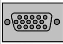
VGA for connecting to a tuner (picture below);

antenna TV connector if there is a built-in TV tuner (figure below);

composite input with RCA connector (tulip);
component input with three RCA tulip-type connectors for connecting VCRs, DVD players (picture below);

audio input for receiving audio signal.
Outputs can be: DVI (see figure in the chapter on the system unit), usually DVI-D or DVI-I for connecting a monitor, HDMI, VGA, DisplayPort, mini DVI, mini HDMI, mini DisplayPort; S-Video; composite; component; WireFire, audio output.
There are cards that connect via USB, but for version 2.0 the quality is still low.
The video card can support following methods:
Mode FSAA(Full Scene Anti-Aliasing) – allows you to smooth out the “staircase” effect that appears when displaying slanted lines. The meaning of this option is that redundant calculations are first made for a higher resolution, then transferred to the desired resolution. However, when drawing horizontal and vertical lines, they may be blurry. First, the SSAA (Super Sampling anti-aliasing) method was used, which is an analogue of the FSAA mode. This method was used until DirectX version 7, then the MSAA (Multisample anti-aliasing) method was used, which has a small amount of additional calculations, but a worse result. Then we returned to the FSAA method again. This mode has several degrees and the user can select the degree he needs.
Mode hinting allows you to change the font if it is subject to rasterization. Rasterization is the process by which a vector image is converted into a raster image. Below are two drawings, one original, the second rasterized, in which the characters have a blurry appearance. Hinting mode allows you to transform the font design to sharper lines.

Anisotropic filtering allows you to get rid of the blur of small details in three-dimensional graphics and has up to 16 degrees. The higher the degree, the better the rendering, but more processing power is required.
Bilinear filtering selects several pixels and then averages them. Used for two-dimensional images.
Trilinear filtering is a development of bilinear filtering and has a different averaging method. Also used for 2D images.
Geometric instancing is a method in which multiple copies are drawn in one pass. That is, usually one object is formed per frame. For figures that are in the distance, they are made as two-dimensional objects and several views of this object can be calculated in one run. As a result, the load on the computing system is reduced.
MIP texturing allows you to calculate an object (obtain a texture) for various types of image matrices. For example, 1x1, 2x2, 4x4, 8x8 and so on. And based on them, make the desired drawing. This method requires more memory to store samples.
When installing a new video cards do not forget to switch the necessary switches on the motherboard and set the appropriate settings in the Setup BIOS. For any changes to the computer, before doing anything, it is necessary to rewrite all settings from Setup and the positions of the switches on the motherboard, and only then replace devices.
Each display can have two mode A: graphic and symbolic. Graphics mode allows you to display graphic images based on the calculation that each point on the screen (otherwise called pixel) displays any one color. All displays have a certain number of columns and rows of these elements. Their number depends on the type of display and will be explained below. Text mode displays a certain number of characters, such as letters, numbers, and special characters. The symbol is displayed as dots in a matrix of a certain size, for example 9 x 16.
There are motherboards that contain video adapters, but they have disadvantages: - due to their versatility, not all display capabilities can be used during operation: if one part on the board breaks (for example, a video adapter), you need to change the entire board, along with the video adapter. There are motherboards that have a built-in video subsystem, but they are almost impossible to modify and are used relatively rarely. When connecting another video adapter, you need to set switches to disable the video adapter on the motherboard or disable the video adapter in Setup BIOS. There are boards that automatically disable the old video adapter when installing a new one. The advantages include lower cost for combined devices than for two purchased separately.
Display standards
Nowadays, the type of standard supported by a monitor is not critical, and is not as important when choosing a monitor as it was ten years ago. Nevertheless, we give their descriptions to get a feel for the stages of development of the video subsystem.
The monitor and video memory work together and support different standards. Modern computers on Windows systems operate in the SVGA standard and do not use earlier standards. Immediately after turning on the computer, it may not be SVGA mode that is used, but earlier standards. Operating modes when programming in languages such as BASIC and Pascal also use early standards for presenting information.
One of the first standards was MDA(Monochrom Display Adapter - monochrome display adapter), developed in the early 80s by IBM. This mode displays two colors: either black/white or green/white without gradation. The MDA card allows you to display 80 columns by 25 rows out of a total of 720 x 350 pixels. (720/9=80 and 350/14=25), in this case it is not the pixels that are addressed, but the familiar place, that is, the place where the symbol is displayed. This mode is quite simple to organize, but it has the ability to display only textual information, not graphical information, while easily readable characters are displayed. This standard is practically no longer used.

The next standard is C.G.A.(Color Graphics Adapter - color graphics adapter), also developed by IBM. In this standard, in addition to text, a graphic mode can also be used. In text mode, 25 rows and 80 columns are supported, and in graphic mode - 640 columns of 200 lines, or 640 x 200 for a two-color image, or 320 x 200, that is, a coarser resolution with a color gamut of 4 colors (out of 16 colors palettes). The display can, in principle, display 16 colors, but only 4 of the 16 colors at any given time. This standard is also practically not used at present. The figure on the right shows the representation of the symbol "B".
In the early 80s a standard was developed H.G.A.(Hercules Graphes Card - graphics adapter), which is also called Hercules after the name of the company that developed it (Hercules). The card is capable of supporting a resolution of 720 x 348 pixels in graphic mode; in text mode, the symbol is represented in a 9 x 14 pixel format, which ensures convenient reproduction of symbols for the eye.
The Hercules card has 128 KB of video card RAM for graphics information. Note that for all text modes, only 2 KB (80 x 25 = 2000) of memory is required to represent information on the screen at the rate of one byte per character, or 4 kilobytes for two bytes per character. In the Hercules controller, in addition to the character code stored in 1 byte (there can be a total of 256 different values), there is an attribute that specifies additional parameters, using another byte. This could be: an underscore (a character with an underscore, for example, “ A"), blinking (the specified character will blink, you can create a chain of characters that will blink periodically to highlight a message), inversion (you can print the symbol, for example, white on black, or with inversion black on a white background).
Standard E.G.A.(Enhanced Graphics Adapter) provides a resolution of 640 x 350 pixels and creates an 8x14 dot or 8x8 dot character matrix, which allows for 44 lines. Although this mode is rarely used by anyone, it has been used to display various types of tables. EGA mode allows you to display 16 colors from a 64-color palette. One of the most important advantages of this card compared to previous ones is the ability to programmatically load the font into video memory, which made it possible to work with the Cyrillic alphabet.
Each subsequent video card of a new standard allows you to work not only in this standard, but also in previously developed standards. Thus, a video card with the EGA standard can also work in the HGA, CGA and MDA standards. However, a CGA card cannot operate in the EGA standard. This principle works not only in hardware, but also in software. All old programs can run on modern computers, but not all modern programs developed recently can be run on old computers, for example, Windows cannot be run on a computer with an 8086 series processor.
Switches on the video cards were used to switch the video card from one mode to another. Considering that many companies use different switches, to determine their purpose, it is necessary to request a passport for this device when purchasing a video card.
For the EGA standard, each color was represented by up to four bits, with each bit stored in different places called color planes. In each layer, one byte represents the characteristics of eight pixels. For eight pixels, four bytes are used, which are in different, non-adjacent places. In this case, it is possible to record information simultaneously in different areas of memory, which leads to increased performance of the video system. For the following types of color representation, when more than four bits are required, a linear organization is used, in which all the information about the pixel is contained in one byte or two adjacent ones.
The EGA standard did not last long. The following standard was soon released - VGA(Video Graphics Adapter), which was introduced by IBM in 1987. The VGA standard provides a resolution of 640 x 480 pixels with 16 million colors. However, in reality, depending on the amount of video memory, the card actually supports up to 256 colors.
Older models had 8-bit cards, which required 256 KB of video memory, but then 16-bit cards with 512 KB of memory began to be produced. These standards were established as uniform for all manufacturing companies.
Next format SVGA(Super VGA - Super VGA) developed without a single standard, so currently different manufacturing companies have different standards for SVGA video cards, although there are many common features. When installing these cards, you must also install special drivers so that you can use the additional capabilities of the video card. For SVGA standards, there is already a higher resolution in the field of graphic images, which can be 1024 x 768 and higher. The mode of presenting text information remains unchanged. The amount of memory required for video cards is calculated using the formula: number of pixels x number of bytes per pixel, see the table below. That is, almost all modern video cards support all the modes indicated in the table. The number of pixels is calculated from the monitor resolution settings using the formula number of pixels = number of columns x number of rows. Standard resolution is 800 x 600 pixels, so the total number of pixels in this resolution is 600 x 800 = 48,000 pixels. The number of bytes per pixel is determined at the rate of 16 colors - 0.5 bytes, 256 colors - 1 byte, 32,768 or 65,536 - 2 bytes, 16.7 million colors - 3 bytes. For example, at a resolution of 640x480, 16 colors require 640 x 480 x 4 (number of bits per pixel) / 8 (number of bits per byte) = 153,600 bytes = 150 Kilobytes. If you need to implement two pages, one for frame output, the other for processing while the image is displayed on the screen, then the amount of video memory should be doubled.
Standard XGA(Extended Graphics Array) supports 1024x768 resolution.
Standard WXGA(Wide XGA - wide XGA) supports widescreen, has a resolution of 1280x720 with a 16:9 screen, also 1280x768 with a 5:3 screen, 1280x800 with an 8:5 screen, for LCD monitors 1360x768 and 1366x768 with a screen of approximately 16:9. Resolutions of 1280xnnn are often used in laptops.
Standard UXGA(Ultra eXtended Graphics Array) is designed for a resolution of 1600x1200 with an aspect ratio of 4:3 and 16.7 colors.
Standard WSXGA+ (Wide SXGA+) is designed for a resolution of 1680x1050 with an aspect ratio of 16:10 and 16.7 colors.
As you can see, they differ from each other in screen resolution.

Each primary color is allocated a different but fixed number of bits (5:5:5, 8:8:8, 5:6:5 or 6:6:4 for RGB). That is, 6:6:4 means that 6 bits are allocated for red, 6 for green, 4 for blue. This standard is used in the vast majority of modern computers. Video memory is usually allocated 1, 2, 4, 6, 8 or more megabytes. Memory with decimal fractional values such as 1.2 or 1.5 does not exist.
The memory, which is inserted into the corresponding connectors of the video card, is structurally made not in the form of SIMM or DIMM modules, but in the form of separate microcircuits.
Microcircuits can be of the following types: GDDR, GDDR 2, GDDR 3, GDDR 4, GDDR 5 (in modern computers). GDDR memory is similar in operating principles to DDR, but has higher operating frequencies and is made not on a wafer, but in the form of microcircuits. GDDR 2 is close in its principles to DDR 2, the differences are in the packaging. GDDR 3 has the same technology as DDR 2, but uses a special technology developed by ATI Technologies that allows for higher clock speeds. GDDR 4 is a more advanced memory, but due to the fact that the performance gain was small and the cost increased, it was not widely used. GDDR 5 was released in 2008 by AMD, based on DDR 3 memory, and also introduced 8-bit wide prefetch buffers.
On old computers The following types of memory were used:
DRAM And EDO DRAM– used in fairly simple video cards;
VRAM(video RAM - video RAM) - dual-port memory. Dual-port means that you can independently write/read from different devices, for example, one for image output, the other for working with the graphics accelerator. In this memory, it is possible to erase a specific sequential data area. However, such an organization does not allow doubling productivity due to the time required to recharge the memory. There are more accelerated types of memory, the name of which includes VRAM: EDO VRAM, CVRAM, SVRAM;
WRAM(Windows RAM) is faster than VRAM and also has a dual-port organization with a 256-bit internal bus;
SGRAM(Synchronous Graphic RAM - synchronous graphics RAM) is dynamic memory that is capable of operating at frequencies of 125 MHz and higher. This memory is specially equipped with the ability to transfer data to adjacent cells in one cycle. It is possible to hardware write-protect certain areas, which allows you to fill large areas on the screen with a certain color;
MDRAM(Multibank RAM) - memory for video adapters, allowing simultaneous access to different areas of memory, with a bandwidth of up to 800 MB/sec. It is organized in the form of independent banks, whereas previous types of microcircuits are organized in the form of a single bank, with a frequency of 125 MHz and higher;
RDRAM(Rambus DRAM) is a synchronous memory that allows transferring up to 500 MB/sec and has great prospects.
There are other types of memory, for example, Direct RDRAM, 3DRAM - dual-port memory, oriented towards three-dimensional applications, CDRAM - which has cached memory on the chip itself, DD SDRAM, ESDRAM and others. Before purchasing, read the instructions for your video card to determine what types of memory it supports.
Currently there has been a transition to standard type memoryDDR, which is used in RAM, which reduces its cost, since such memory is produced on a mass scale and has a low cost. In addition, if necessary, it is easy to replace.
The most important characteristics of these modules are the frequency in megahertz (MHz) at which they operate; the higher this value, the better. Maximum throughput is measured in Mb/sec, the higher it is, the better.
Modern video cards use so-called accelerators, that is, the board additionally has a graphics (from the word graphics) processor, which takes over some of the functions of the central processor and performs operations such as creating and drawing geometric shapes, filling them with a certain color, shifting and copying screen fields, operations with three-dimensional graphics , if operations are performed in graphical mode. When working in Windows applications, such maps are called cards with Windows accelerators. When working with DOS applications, such a card usually does not use all the capabilities, so the speedup may be small.
Let's take a closer look at the technologies used in graphics accelerators. As you know, the image of an object when creating a three-dimensional scene is divided into elementary cells - polygons. This is the first task that is performed when creating three-dimensionality - determining the relative position, as well as the degree of illumination of such polygons. After this, the back edges are removed, which is called Backface Cutting, then the surfaces hidden from the user’s eyes are excluded, which in turn is called Hidden Surface Removal. The next task for the GPU is processing information about the so-called object depth, Z-coordinate. This is where data is compressed and redundant information is eliminated. The use of new technologies Hierarchical Z, Z compression, Fast-Z clear provides a significant increase in performance.
To improve the quality of the created image, another new technology is used - Truform. Its essence lies in the fact that the frame of an object is divided into a significantly larger number of primitives, and at the same time, data on the normals to the sides of the primitives is used in the construction of a new surface. This surface is called N-Patch and has smoother curves, which improves the quality of displayed objects.
In order to improve the quality of texture rendering when creating the surface of objects and creating light and shadow effects, the new Smartshader technology is used. Another new technology is full-screen scene anti-aliasing (Smartshader or similar FSAA). In this case, the entire image is preliminary. before being displayed on the screen, it is slightly shifted by some distance. And finally, the color of the pixels is calculated based on eight neighboring points, as well as the location of the element inside the scene.
The following standards have emerged but have not received much development: TIGA, XGA(Extended Graphics Adapter - extended graphics adapter) ,HiRes. The monitor displays the information that the video card transmits to it. Therefore, it is better to buy these two devices together to be sure that they fit together.
The following modes can be supported in video cards:
- HiColor capable of reflecting 32,768 colors. In memory, a single pixel occupies 15 bits, in which each of the three primary colors (red, green and blue) occupies 5 bits. Any visible color, including white and black, can be reflected using the three primary colors. This is enough to display the entire color palette.
Mode Real Color support 65,536 shades, 16 bits are allocated for each pixel.
Mode True Color supports 16.7 million colors. In this mode, each pixel contains a 24-bit word. The human eye can perceive about 2 million shades. However, not all monitors actually reflect so many shades. Video cards require the installation of special drivers that allow you to use additional features of the cards. Therefore, when purchasing, pay attention to the availability of floppy disks or CD-ROMs with drivers. Drivers were previously of several types: for working in DOS, Windows 3.11, Windows 9x. Currently for work in Windows 98, Windows ME, Windows 2000, Windows XP and more modern Windows Vista and Windows 7. It is desirable that all these drivers be available.
Many modern video cards allow you to output images directly to two monitors, and some even on three screens. It has almost become standard for video cards to have a video output for connecting a home TV to a computer.
One of the new technologies, Lightspeed Memory II, has a built-in memory controller in the form of four separate blocks that ensure image processing in parallel mode. This architecture allows you to increase system performance and reduce the time for pre-processing video data.
Inserting a card
Inserting the board. In order to insert the card, you first need to select the slot where it will be installed.

On the back side of the system unit there are plugs attached to the case. If you have chosen a place where the board should be located, then remove the plug and install the board in this place.
The figure above shows an approximate appearance of the video card. Other boards, for example, sound boards, have the same structural elements. When you take the board with your hands, it is advisable to hold it by the edges of the panel. Your body may be charged with electrostatic electricity, so touch ground before working inside the system unit. This could be a central heating radiator. But the contact must be in a place where there is no paint. You can clear the appropriate area of paint. As a last resort, touch the computer case.
When working, take your time and take precautions. Next, follow these steps: Turn off the computer, disconnect the wires on the back wall of the system unit, mainly the power cords and the cable to the old video card. Other wires can be left if there is no need to move or transfer the system unit. Open the system unit case, unscrew the screws securing the board to the case and remove the old board.
If the new card must be inserted into a different slot, then cover the old hole with a protective panel and secure it with screws, remove the plug in the place where the new card will be installed. If necessary, install jumpers and switches on the video card, and possibly on the motherboard. On a motherboard, this is possible when switching from a color monitor to a black and white one and vice versa.
Install the card into the slot. It may take a little force to force the card into the slot. In this case, you need to ensure that there are no distortions in the installed board. If you are sure that the card will work, then you can tighten the screws securing the card to the system unit stand. In this case, on the back wall of the system unit there is a board connector where you connect the information cable to the monitor. The types of connectors are described earlier, note that very old boards have a 9-hole connector (EGA).
Other boards, for example, sound or modem, are inserted in the same way. Then you need to close the system unit with a lid and connect the wires. The first connectors for connecting a monitor to a computer used a DB9 connector with nine pins, then the DB15 began to be used, which has 3 lines for an analog signal of primary colors, horizontal and vertical scanning of signals, that is, five signals plus five ground lines to them. The rest: one is not used and four are used to receive signals such as monitor parameters from the monitor to the computer. There may be other connectors for modern devices, such as five cables for high-end monitors.
Experienced users install the fastening screw and close the cover of the system unit after testing the video card, but it is better to close the unit with the cover before testing - this is a note for inexperienced users.

The left connector is the oldest and most common and is an analog VGA monitor output. To the right of it are two types of connectors for transmitting digital information: DVI-D and DVI-I (or otherwise called DVI). At the bottom of the DVI connector is a cross-shaped connector, not present in DVI-D, containing pins for analog transmission. Modern monitors may have two connectors: analog (VGA) and DVI. The monitor can be connected to any of them. In addition, there may be connectors for connecting to a VCR (input and output). If both the monitor and the video card have both VGA and DVI connectors, then it is better to connect the data cable through the DVI connector.
Other types of connectors are described earlier.
Next, you should turn on the computer. If the screen does not work, review the settings again, you can remove the card and install it again, there may have been poor contact in some places, and turn on the computer again.
Enter the BIOS and set the parameters necessary for the operation of the video subsystem, for example, the Primary Display parameter for VGA. Save your settings, exit the BIOS and restart your computer. At the final stage, you can test the video card and configure it, install drivers from a floppy disk or CD-ROM drive, or configure it using Windows tools.
Problems. If the screen does not light up, then you need to try turning the brightness and contrast buttons, maybe they are turned off (this applies to monitors with a CRT (cathode ray tube)). If there are beeps after turning on, this means that the Post program, which runs after turning on the computer, was unable to display a message on the display. In this case, check all connections (from the display to the rear wall of the system unit, connecting the monitor to the network), the correct connection of the video card, and the BIOS settings.
If the monitor does not work, then first check the cable connections to it; you can insert another cable. Check whether the video card is installed correctly, maybe remove it and put it back in, first cleaning the connector from dust if it has accumulated there. You can try connecting the monitor to another computer. But under no circumstances should you disassemble the monitor case yourself; entrust this to a specialist. If the light on the monitor is on, then it is connected to the network. Maybe try temporarily disconnecting other devices, such as the sound card, modem, network card, to check if there are any conflicts in their use. If the menu on the screen is not presented correctly, then the error may be in the driver, then it needs to be reinstalled.
When one of the colors is displayed in a different color on the screen, the contact of the card connector is most likely broken. If the monitor has fewer colors, check the amount of video memory or the serviceability of the chip on the card.
When several images are visible on the screen, it is difficult to make out what is displayed on the screen, then problems with frequency sweep are possible. In this case, restart the computer, set a lower resolution (In Windows 9x, when loading, press the F5 key after the message about starting Windows 9x appears). This will switch to the “Failure Protection Mode”, in which the standard VGA driver is loaded - change the driver or set a lower resolution.
Sometimes you need to install additional memory on the board. To do this, remove the board as described earlier, place the card with the electronic components down on an antistatic mat and insert the chip into a special socket on the board, following the manufacturer's instructions, which usually write that you need to align pin “1” with the identical “1” on the chip and press the chip into the socket. Do not touch the terminals of the microcircuit, as this may damage it. After installing the chip, you should insert the board back.
Some boards have the ability to work with the format MPEG(Motion Picture Expert Group), which allows you to convert the compressed encrypted format of video films into a format that displays the image on the screen. Since a movie contains a lot of digital information, it is compressed to use less memory. There are various formats for this, one of the most common is MPEG.
If other formats are used, this capability is provided by the video card. To work better with video images, you need to have good RAM and fast buses, such as PCI-E.
Display
Display, also called monitor, is one of the most important components of a computer. The most common types of monitors are based on cathode ray tube, liquid crystal, projection, stereo glasses and other types. Special attention should be paid to all those devices with which the user works, namely: monitor, keyboard, mouse, since it is with them that direct contact occurs. Therefore, when buying a computer, pay special attention to the monitor. If you have to work with it for quite a long time during the day, then it should be comfortable and not cause eye fatigue. When purchasing, you may like a certain monitor, but you need to keep in mind that you won't feel tired within a few minutes. Therefore, pay attention to its characteristics, first of all, the type of monitor, line frequency, screen size, etc. Pay special attention to this: if you do not need to work with color, then it is better to purchase a black and white monitor, which will tire your eyes less. It’s not for nothing that savings banks have black-and-white monitors, which are less irritating to the eyes and have less electromagnetic radiation. Black-and-white monitors have better clarity, are cheaper, but, unfortunately, they are not actively developed, so there are no such monitors with higher resolution.
Below we describe mainly color monitors and those of their characteristics that are not used to implement color and are similar to the characteristics of black-and-white monitors. If the signal that controls the brightness of the electron beam is analog, then the monitor is called analog, and if the signal is based on digital information, then the monitor is called digital. Digital monitors were used in the first adapters (CGA, EGA).
All monitors can be divided into two groups: cathode ray tube (CRT) and TFT monitors. Previously, CRT monitors were used, but recently liquid crystal (TFT) monitors have become the most popular. Previously, computer monitors could not be used as a TV and there were two screens at home, one for the computer and the second for the TV. Modern LCD monitors can (not all) work as both a TV and a computer monitor. You can determine that a TV can work like a monitor by looking at the back wall and seeing the presence of connectors for connecting to a computer (for example, VGA). Typically, the device has several connectors (analog and digital).
Main characteristics display are:
- diagonal size, measured in inches. The most common recently were 14-inch screens, then 15-inch ones, but recently manufacturing companies are starting to produce more and more 19-, 20- and 21-inch and more-inch monitors, since they make text easier to read and are more convenient for the user. However, despite the fact that the monitor’s specifications say the screen diagonal size is 17 inches, in fact, in some cases the visible image can be 16 inches (for CRT monitors, for LCD monitors, the parameters indicated in the manual and the actual parameters are the same). This is because the tube itself measures 17 inches diagonally, but the edges of the tube are not used to display the image. Moreover, different companies may have their own values. You can buy a monitor with a visible part of 13.7 inches as a 15-inch, or you can buy a 13.5-inch monitor as a 14-inch. The standard values for this parameter are 14, 15, 17, 19, 20, 21 or more inches. Tubes with a diagonal of 21 inches or larger are used in publishing systems;
- permission- number of points horizontally and vertically. Each dot is called a pixel and can display one color by mixing red, blue and yellow. The screen size must match its resolution. If the screen is small, then high resolution is not required. For example, the 1024 x 680 size for a 14-inch screen is rarely used due to the fact that the characters become small and working on the screen for a long time can lead to headaches. This resolution is recommended for a screen measuring 17 inches diagonally.
The following main resolutions can be: 640x400, 640x480, 720x 400, 720x 576, 800x600, 832x624, 832x 634. 848x 480, 1024x768, 1140x900, 1152x 864, 1280x7 20, 1280x768, 1280x800, 1280x960, 1280x1024, 1360x768, 1366x768, 1400x1050 , 1440x900, 1440x1050, 1600x1200, 1680x1050, 1920x480, 1920x1080, 1920x1200; Note that the resolution of 640x480 is the VGA standard, 800x 600 is SVGA, 1024x 768 is XGA, 1280x 768 is WXGA, 1600x 1200 is UXGA, 1680x 1050 is WSXGA +;
Possibility of using the monitor for three-dimensional images. Typically, a 3D Ready monitor has a frequency of 120 Hz (60 Hz for each eye), glasses must be purchased separately;
LCD matrix type, which can be: TFT IPS, TFT S-IPS, TFT H-IPS, TFT UH-IPS, TFT E-IPS, TFT P-IPS, TFT MVA, TFT PVA, TFT S-PVA, TFT TN ;
A type of CRT monitor, which can be: with a shadow mask, a slit mask or an aperture grille (what it is, see below), moire suppression function (line smoothing);
- LED -backlight(for liquid crystal monitors) allows you to display better colors, the thickness of the screen is reduced and requires less power consumption, but is more expensive than usual;
- power unit either built-in or separately made. Only for LCD monitors, since CRTs have all power supplies inside the monitor;
- monitor rotation 90 degrees (for liquid crystal monitors), support for ISO 13406-2 standard (standard for monitor quality: brightness, contrast, viewing angles, number of defective pixels. For the first class - no dead pixels, the second 2-4 dead pixels and 4-10 subpixels, that is, one of the colors), height adjustment, Russian menu,
Maximum and minimum horizontal and vertical frequency sweeps in hertz. The higher the better;
- touch screen, in which touching the screen with a finger causes an electrical signal, which allows you to determine the coordinates of the touch;
Number of accepted television channels(up to 2000), support for 24p True Cinema, which allows you to watch a movie at 24 frames per second, Skype - the ability to make calls through the program of the same name, support for the MP 3 standard, flash memory for storing recorded programs, Dolby Digital support for sound playback, to play audio files;
- series. Recently, monitors have begun to be divided into classes: economic, professional, graphic, gaming and business. However, there are no clear standards for them yet and everyone can determine their own requirements;
Availability connectorUSB, that is, a USB hub to which you can connect additional devices, for example, an MP 3 player, a digital camera, etc.;
- vertical field of view(for liquid crystal monitors) (45 – 180 degrees), that is, at what angle the picture on the screen is clearly visible, that is, the contrast is reduced to 10:1. It's normal if 160 degrees;
- horizontal viewing area(for liquid crystal monitors) (70 – 180 degrees), that is, at what angle the picture on the screen is clearly visible, that is, the contrast is reduced to 10:1. It's normal if 160 degrees;
- dynamic contrast(for liquid crystal monitors), defined as the brightness of the white field to the dark field at maximum brightness, for example, 1000:1 and simply contrast (800-10,000). Contrast the ratio of the white field at maximum brightness to black at minimum brightness (a good value is 500-600);
- brightness(65-610 cd/m2) represents the intensity of the screen. LCD monitors have an indicator of 250-300 cd/m2, CRT - 80-100 cd/m2;
- color calibration, which allows you to set the shades. Using this parameter, you can achieve accurate color reproduction;
- response time(from 1 to 60 ms) (for liquid crystal monitors), that is, the period of time after the control signal is applied, after which the color changes from white to black. Less is better. Lower values are required for gaming;
Availability convergence functions(for CRT), in which there is no deflection of the rays and, as a result, there is no color border at the border of the sharp transition from a bright background to a dark one;
Mode "picture in picture", in which two images are displayed on the screen, one in full screen, the second in a small window. Availability multiscreen delayed viewing recording timer, in which you can record a program when you are not at home
- embedded devices: microphone, webcam, subwoofers, optical drive (Blu-Ray or DVD player), including speakers (1-4) and their power, the higher the volume, the less distortion;
Entry and exit connectors(presented in the description of the video card), including audio connectors, for example, for connecting headphones, Bluetooth, Wi-Fi;
- display type, more precisely, the format that it supports. The first displays supported the CGA, EGA, VGA format, but now such formats are already outdated and displays are produced mainly in the SVGA format. However, all later format displays support earlier formats. The main characteristics of the formats used are described in the previous paragraph. This parameter was important for older monitors. For modern monitors this parameter is not important; the important parameter is screen resolution;
- grain size(for CRT displays). The optimal grain size is 0.26 mm. The grain is the distance between the holes in the shade grid. Some authors define it as the distance between the nearest subpels of the same color. In this case, for an aperture array this parameter can be called the stripe pitch. It's better when it's 0.21. With a larger grain size - 0.28 or more - it is clear that the characters consist of dots, and working with this text is inconvenient. There may be indicators - point pitch horizontally, vertically, diagonally;
- number of colors. For a point (or pixel) on the monitor screen in different modes, a different number of colors is displayed. For example, 16, 256, and so on. The more colors displayed on the screen, the better. Almost all modern CRT displays display 16.7 million colors, liquid crystal displays can have 18-bit addressing (262 thousand colors), 24-bit – 16.7 million colors;
- power consumption in standby mode (1-10 W, usually LCD monitors consume 1-2 W, CRT 5-10 W), in sleep mode (0.5-3 W), during operation (5-320 W, LCD consume on average 35-40 W);
- throughput, bandwidth determines the speed of information transfer from the card to the monitor and is characterized by the maximum number of pixels displayed on the screen (30-400 MHz). The higher the speed, the better;
- display type. It can be of two types: 1) interlaced and 2) lowercase (in systems with progressive and non-interleaved technologies). Linear displays lines sequentially one after another, that is, first, second, third, fourth, and so on. Interlace displays through a line, that is, the first, third, fifth, ... second, fourth line and so on. Both modes have their pros and cons. The advantage of interlaced scanning is that moving objects are better perceived by the eye, while stationary ones are worse. By the way, this is the type that is used in television. The advantage of the second type is a clearer perception of still images, which are often found on the screen. Since the human eye perceives the picture as motionless at 75 Hz and above, for interlaced screens the frequency must be twice as high in order not to perceive flicker; on the other hand, with interlaced scanning, less information needs to be sent to the monitor. So the next parameter is quite important for monitors;
- frame frequency. The higher it is, the better for high resolutions. Must be at least 75 Hz;
- type of protection. Today, all displays are produced with a protective coating on the screen (for CRT monitors). However, additional protective shields will help reduce electromagnetic radiation and will also reduce screen glare. Currently, there are two most common standards: MPR-II and more severe to radiation - TSO-92, TSO-95, TSO-99, TSO-03, TSO-06, TSO-5.0 (2009), TSO-5.2 ( 2010). The later the standard, the stricter and better it is for the consumer. The display must implement one of these standards. For LCD monitors, an antistatic coating is used, which prevents dust from sticking to the screen, as well as a glossy coating, which improves brightness, contrast, disadvantage: glare and high soiling (dust sticking). The housing can be moisture resistant for use in damp areas;
- multimedia displays, which, in addition to the screen, contain output speakers and may contain a microphone;
-monitor dimensions;
- environmental conditions, which include a range of temperature (often 0-40 0) and humidity (usually 10-80%).
Don't forget that the monitor must match the video card, otherwise it will not take advantage of many capabilities or, when the card is higher than the display's capabilities, will fail. If the low consumption mode is not supported by one of the devices - BIOS, video adapter or monitor, then the mode will not work.
Cathode ray monitors.

Typically, information is displayed on the screen using a monitor with a cathode ray tube (CRT) (Catode Ray Terminal), also called a CRT (Cathode Ray Tube). When the cathode heats up, the electron gun releases a stream of electrons called an electron beam. The beam is directed to the other end of the tube and hits the screen, which is coated with a phosphor. The phosphor begins to glow, but does this for a certain time, optimally until the next time the beam hits the same place. To ensure that the beam passes across the entire screen, focusing coils are used, which, under the influence of an electric current, create a magnetic field that deflects the electron beam. In this case, the beam passes across the screen line by line, first along the first line, then the beam is extinguished and goes to the beginning of the second line, passes along it and then along the following lines. After passing the last line, the beam is also extinguished and returns to the beginning of the first line, after which the cycle continues. On each line there is a certain number of dots (pixels) that cause a ray to glow in a certain color, which will be explained further. It is clear that in order to display an image on the screen, you must first form it and display it point by point. This approach is called raster. With the vector approach, which is used in oscilloscopes, the beam runs across the screen along the contour of some figure that must be depicted. There were also vector displays for computers, but they were not widespread and have so far been forgotten.
To form a color image, a cathode ray tube has three electron guns, each of which is responsible for its own color (red, blue and green). In front of the screen there is a Shadow Mask, which is a metal plate with holes, one hole for each pixel. The beam hits the corresponding sub-cell, as shown in the figure. ( Subpal- an area on the screen corresponding to one of the three primary colors, with three sub-palms of different colors representing a pixel). The three electron guns are arranged in a triangle, as are the subpels. If the holes are located in the form of ellipses, then this is an improved shadow mask (Enhanced Dot Pitch), in the form of rectangles - a slot mask, in the form of lines - an aperture grid. The aperture grilles are made of a special material (invar) that does not expand when heated. In this case, the subpels will be in a different position relative to each other, for example, at the aperture grille in the form of lines, three guns lie in a horizontal plane, one next to the other. With an aperture array, the electron gun and color spots are arranged in a line, then the rays of each of the guns fall on the colors that correspond to them. This technology is called trinitron.
A monitor that can operate in several standards is called multi-mode, multi-frequency, plug-and-play, multi-scan, etc., depending on the manufacturer, where each has its own name for this term. Almost all manufactured monitors are multi-frequency.
Russification, that is, the ability to display Cyrillic characters on the screen in modern displays is not required, since they work in graphical mode (Windows system), and Russification is provided by the system itself. When working in DOS, there are special programs that Russify characters, that is, it is provided using mathematical, not hardware. In modern monitors, Russification means the presence of menus in Russian.
Due to the fact that a computer user mainly sits in front of a display screen, selecting a good monitor is one of the important tasks, since the strain on vision when working in front of a screen for many hours is quite large. As a rule, it is necessary to select a display with a frequency of at least 70 Hz and a grain size of at least 0.26. The quality of the phosphor covering the screen plays an important role. Each point on the screen must glow for the time required for the electron beam to pass through the entire screen and return to that point. If the dot glows for less time, then the image flickers, if longer, then colors overlap.
LCD monitors are based on a different approach than cathode ray tubes. They are smaller in size, have a flat screen, do not produce electromagnetic radiation like CRTs, have less weight and power consumption, but are more expensive than CRTs. These screens are mainly used in laptops, but recently more and more are being produced for desktop computers. Unlike cathode ray tubes, they have the same field size as described in their specifications, not smaller, and they do not require screen adjustments.
Principle of operation such displays are as follows. The bottom layer contains special miniature light bulbs (light sources) with low power consumption. Next come two layers: linear and vertical polarizers, between which there are molecules of a special liquid crystalline substance. The vectors of the vertical and horizontal polarizers are rotated relative to each other by 90 0 . In the absence of voltage, the polarization between the plates has a direction of 90 0, which transmits light; in the presence of voltage, polarization does not occur and light does not pass through the polarizer.
If the pixel consists of one cell, then the screen is black and white, if it consists of three sub-cells, then the screen is color. There is another approach that uses three layers that produce light corresponding to one of the three primary colors. The disadvantage of this method is the need to use a strong light source, since the light passes through several surfaces and becomes less bright. The image is regenerated several times per second, while the pixel persistence time is quite long and changes with voltage changes. These screens are called passive matrix because the color change is regenerated when a cell (pixel) is accessed.
The following view has the ability to update the top and bottom of the screen in parallel and is called DSTN. To change the voltage, voltage is applied to the pixel in the row and column where it is located, causing horizontal and vertical stripes to appear on the screen. On modern screens TFT(Thin Film Transistor) each cell has its own transistor that controls it. Color panels use three sub-palms as usual. The pixel circuits have their own memory, so the color is held until there is a new voltage value. Such monitors use digital signal data rather than analog and are digital. Therefore, if a desktop computer has a video card that converts digital data into analog form, then the reverse conversion from analog to digital takes place in the liquid crystal display. If double conversion occurs, image deterioration may occur. In addition, these displays are very good at displaying images at their appropriate resolution. For another resolution, the image quality will be normal if it is a multiple of the existing one, if not, it will be poor. This does not happen with CRTs, since individual pixels may be partially illuminated.
The next parameter is viewing angle. Since it is smaller in LCD monitors than in CRTs, that is, when looking at the screen from the side, the image is not visible, especially on DSTN screens. Therefore, it is advisable to keep the screen perpendicular to the person’s eyes. Modern TFT monitors already have a high frame rate, reaching 70 Hz or more. When purchasing an LCD display, you need to check the screen to ensure that all pixels are functional. To do this, change the brightness from dark to light for the entire screen so that there are no dark or light spots.
TFT screens are also called active matrix. Many of the characteristics of LCD screens are similar to CRT monitors, but there are also differences. So, to form an image, the voltage of each point (pixel) changes and, since it does not contain a phosphor, the glow of which disappears over time, the image is of higher quality, without flickering.
In addition to these types, there are plasma monitors, in which the screen is divided into cells with gas, which begins to glow when voltage is applied to it, but they are quite expensive. There are other, more or less exotic types, for example, a virtual reality helmet, there are screens that, when clicked, perform the function of a mouse, and so on, but they have not yet found widespread use. There are touch screens in which, when you touch a finger, the system recognizes this action using a special sensitive membrane on the screen or electromagnetic radiation sensors.
There are other types of displays, for example, electroluminescent monitors. Projection devices are also produced that display an image on a screen while simultaneously increasing its size. They use different principles, most often using liquid crystal panels through which light passes. With the help of a lens, the image is enlarged and then appears on the screen. You can shine light on one panel, which reproduces all colors, or on three different panels of primary colors and combine the resulting images. There are quite a lot of technologies that are in their early stages of development.
One of the most promising is OLED technology(Organic Light Emitting Diodes, which means “organic light-emitting diodes”). Unlike LCD displays, which use backlight lamps, the principle of light emission is used here when molecules transition into a state with a high unstable energy level with the participation of two charge carriers - electrons (n-region) and so-called holes (p-region), which represent free spaces in the crystal lattices of atoms of organic substances.
Previously, a similar principle was also tested in the manufacture of calculator displays and other devices, but then, in the late fifties of the last century, silicon was used as a semiconductor material, which led to the need to use a fairly high voltage.
As a result of long research, the following technological process was developed. First, a layer of copper plastocyanin is applied to a transparent indium oxide material, and layers with a p-region and a p-region are applied to it. Finally, a mixture of magnesium and silver compounds is applied. The principle of constructing a matrix for the screen is the same as that of LCD displays.
Such monitors have a number of advantages over their LCD counterparts, first of all, their color rendition is much better, and the viewing angle is higher, up to 160 degrees. In addition, these matrices consume significantly less electricity, are technologically cheaper and, in principle, allow one to obtain significantly better screen resolution performance. To top it all off, such screens are very flat due to the absence of backlight bulbs, and the response time to voltage changes is 1000 times faster than that of LCD matrices. The only limitation on the use of such technologies is the short service life of the resulting screens, on average up to one and a half years.
CRT screens coated with high-quality phosphor appear high-contrast, clear and flicker-free. In addition to cathode ray displays, in 1997, liquid crystal displays measuring 14 inches or larger for desktop computers began to be produced.
Flat screen monitors provide less glare, less geometric distortion, and are therefore less straining on the eyes. If you have to work only with text, then it is better to purchase black and white monitors, which are cheaper and less harmful to the eyes and health. When working with the monitor, pay attention to where it will be placed. If it is placed where sunlight falls, the phosphor will fade over time, which will reduce the display's operating time. When working with a monitor, you should make it a rule to take regular breaks to rest your eyes.
The monitor may have an MPR II standard, which was adopted in 1990 and includes limits on the amount of electrostatic charge. TCO 92 is a more stringent standard and additionally covers ergonomic indicators. TCO 95, in addition to the previous restrictions, includes restrictions on noise, heat generation and other parameters. TCO 99 is an even more stringent standard that tightens the requirements for electrostatic charge, magnetic fields and other parameters.
Do not keep devices that produce strong electromagnetic fields near the monitor. Monitors are usually equipped with means for demagnetization in the form of a special coil located along the contour of the screen. It begins to function when the monitor is turned on, sometimes while working with the monitor. Therefore, the speakers that are mounted on the monitor must be specially designed for this purpose, with radiation suppression devices. When installing devices with strong magnetic emissions, such as speakers, color spots may appear on the screen. The strongest radiation from the monitor comes from its back and sides, so you need to make sure that, if possible, no one is sitting behind the monitor.
A good monitor will converge the rays so that white lines appear white rather than rainbow-colored. You especially need to pay attention to the convergence of the rays at the corners of the screen. In addition, it is advisable to check how the image looks when the brightness is increased. If this happens, it means that the power of the high voltage source is insufficient. You also need to make sure that there is no pulsation of the image or colored fringing of the image, which indicates poor convergence of the rays.
Adjusting a monitor can be a tricky task, so when purchasing, you need to make sure that the monitor meets all requirements, the image is clear, and there is no shaking or other unpleasant effects. If the seller says that all this can be set up at home, then it is better to ask him to do it on the spot, upon purchase, since the monitor may be faulty. In addition, setting it up at home can be an overwhelming task, and taking it for warranty repairs can be a tedious task.
The first monitors had potentiometers to adjust the basic display parameters (brightness, contrast, etc.). Then buttons began to be used, that is, there was a transition to digital control, and then it became possible to organize a menu on the display screen and store basic parameters in the memory of the display itself.
When purchasing a monitor, pay attention to distortions that may occur when displaying geometric shapes, such as circles and rectangles. In a rectangle, the lines should be straight, not concave. The circle should be a circle and not an ellipse, the same applies to a rectangle. Many modern displays have controls that allow you to display the image without distortion; it is best to use a test pattern for these purposes, like on television. If the controls do not set a normal image, then you have a defective display.
The monitor should easily switch from one mode to another without any problems. Sometimes there are bright short-term flashes on the screen. These flashes can be seen when booting into Windows 95. The higher the quality of the monitor, the fewer of them there are.
The next parameter is the distortion when transitioning from a dark color to a light tone. The less contrast it is, the better. Another parameter is the power consumption of the display, the lower the better. Many modern displays implement an energy saving mode, when the picture does not change, the display switches to more economical energy consumption, which can be found in the device passport.
The display must be coated with an anti-glare compound that does not reflect sunlight. It is much more profitable to buy a monitor with good protection than to buy a bad monitor with a protective screen, since a good protective filter is quite expensive.
The display generates heat during operation. If your display is hot, its lifespan is short. The monitor should have plenty of ventilation holes for good cooling. When installing the monitor, you need to connect two cables: power and data. The first, as a rule, is connected to the network (in older computers to the rear wall of the system unit from the power supply and, accordingly, to the display). The second is to the video card and, accordingly, to the display. Before turning it on for the first time after the monitor has been outside in winter, it is necessary for it to warm up, that is, you do not need to turn it on for two hours. You can find out more about this in the user manual, which describes the characteristics, connections and precautions when working with it.
Monitor being cleaned vacuum cleaner through the air holes in the housing. Before cleaning, you must disconnect the display from the power supply. When cleaning with a damp cloth, be careful not to allow liquid to enter the housing and cause a short circuit. You should not open the monitor yourself; it is better to entrust this to specialists. The screen should be cleaned as specified in the instructions for this device. Many monitor screens are coated with an anti-reflective coating, and removing the coating in one place destroys the entire layer. To clean such surfaces, detergents are greatly diluted. Do not use liquid or aerosol cleaners. One or two drops and a damp cloth are enough. You need to wipe with light pressure, otherwise there may be mechanical damage to the screen. Do not clean the monitor while it is on, otherwise you may damage it. Wait five minutes after it turns off and then start cleaning. To do this, spray the special liquid not on the monitor or near the side ventilation holes, but on a rag, otherwise liquid particles may get inside the display.
On the front of the display There is, as a rule, an indicator that the monitor is connected to the network, a power button and several controls: - contrast,  - brightness, as well as image frame shift - up and down, - left and right, - horizontal size control, - vertical size control and image edge linearity control. Colors can be adjusted using special programs. To shift the image on the screen, when the screen is not warmed up, you need to leave stripes on four sides, since when the screen is warmed up, the image may expand. Please note that if the monitor operates at high frequencies, its service life will be reduced.
Modern monitors have a built-in menu for adjusting parameters. Moreover, some modes, for example, brightness and contrast, can be adjusted both in the menu and with separate buttons.
In order to enter the menu, you need to press the corresponding button on the monitor, and different models may have different designations. Often there is a button labeled Menu or . In order to select a menu item, you need to use the appropriate keys, for example, , , and or “+” and “-”. In order to exit the menu mode, you need to press a button like Exit or Exit ().
In addition, there may be an indicator near the buttons that lights up when the monitor is connected. Typically, if the monitor is turned off or in sleep mode, the indicator will be amber or flashing. If the monitor is turned on, the indicator lights up green. The indicator may light amber when the settings are changed, that is, after entering the menu.
Types of pictograms quite a lot in different models. For example, here are some of them: - brightness; - contrast; - adjusting image width; - image height adjustment; - fixing the image for fine adjustment (helps to get rid of image flickering; - horizontal screen position; - vertical screen position; - convexity of vertical borders; - elimination of pincushion distortion; - correction of image distortion; - adjusting the parallelism of vertical borders; - restoring the factory configuration , which can be image geometry (Geometry) and color (Color); - setting the “warmth” of colors, which can be custom, red, blue; - color control, in which you can set the settings for red (R), green (G ) or black (B); - selecting a language for the monitor settings menu; - horizontal and vertical screen position; - setting the time in seconds after which, if not accessed, the menu will disappear from the screen; - displaying the frequency, polarity of signals and resolution levels, in which nothing can be changed, since these parameters are displayed only for user information; - - moving a frame with an image across the screen; - changing the frame size simultaneously horizontally and vertically; , , , - correction of various types of distortions; - color change on the screen: red, green and blue; - elimination of Moire, which removes distortions in the form of concentric arcs or circles, - used when the image is blurry; - improved cleanliness of dark areas around the edges of the screen; - improving image transparency; - demagnetization, during which the monitor may hum for several seconds, which is normal.
Display Installation It's quite simple to make. Place the monitor in the place where it will be located. It should be a flat surface that prevents the monitor from falling. In addition, the slots and openings of the monitor should not be blocked, for example, in built-in cabinets, away from heating devices. Many displays come with a stand to make it easier to rotate the monitor, so when installing, be sure to include a stand as well.
Then you need to connect the cable to the network. Old displays were connected to the power supply (a connector on the back of the system unit), but this connection increases the load on the unit, so it is best to connect it to an electrical outlet. The second (information) cable is connected at one end to the monitor, and at the other to the video card, the connector of which is located at the bottom on the rear side of the system unit. The connectors are special, so it is quite difficult to plug into the wrong connector. After connecting, you should turn on the computer and install the drivers. To do this, use the appropriate modes of Windows systems. In addition, the actions that need to be performed are usually described on floppy disks or in the documentation for the monitor. If the display screen does not light up, then you need to try turning the brightness and contrast buttons, maybe they are turned off.
When working with wires Observe the following rules: when connecting/disconnecting, do not grasp the wires, but the plugs or plug; do not place anything on the wires or lay them where people can walk, so as not to damage them; When connecting the wires, do not tighten them, but leave them a little loose, especially for the wires leading to the monitor, since it is often rotated during operation. If the monitor does not work for a long time, it is better to disconnect it from the power supply.
When working with a monitor: Keep ventilation openings open; when moving from the cold, wait two hours before connecting so that the monitor temperature is equal to room temperature; Never disassemble the monitor! do not install the monitor in direct sunlight and keep away from heating devices; Do not install the monitor without a stand on a soft surface such as rugs, as the ventilation holes at the bottom of the monitor will be blocked; If water gets into the monitor, turn it off immediately; Unplug the monitor if you do not plan to use it for a long time. Do not insert foreign objects into the openings as they may cause a short circuit. Do not place objects that could spill liquid, such as a cup of water or small objects, on the monitor. When you turn on the monitor, you may sometimes hear a clicking sound, but this is not a sign of damage. If you hear an unusual sound, smell, or smoke, there is something wrong with the display. In this case, contact a warranty workshop or repair company. Sometimes you hear a clicking sound when a certain program is running, often this means that the program is trying to use a mode that the monitor does not support. In this case, you need to configure the program settings to a different video mode; if the monitor remains on from time to time without working with it, it is best to use the screen suppressor that is available in Norton Commander and Windows; When working with a computer, stay at least 50 cm away from the screen; since the screen and protective filter collect dust, they need to be wiped from time to time using an antistatic solution; It is not advisable to install the display near a window or, if it is installed there, close the curtains; organize the lighting in the room using additional light sources so that the contrast between the screen and the lighting in the room is minimal; Take a break from work from time to time, do eye exercises more often, and blink while working so that the cornea of the eye is moisturized.
Some tips. If there is no image on the screen and the power indicator is not lit, check the power cable. If the indicator is on but there is no image, try rebooting.
If after a reboot a text image appears indicating the connected devices, and then the image disappears, boot into safe mode and adjust the display settings, including screen resolution and video card frequency.
If there is no image, but the indicator is either blinking, amber, or off, the screen may be in sleep mode. Press any key on the keyboard, preferably with arrows or Page Up or Page Down .
If the image is shaking, then check that there are no objects near the monitor that generate electromagnetic fields, including speakers, electrical wires, electronic clocks, radios, etc. In addition, the cause of the image shaking may be a mismatch between the parameters of the video card and monitor (interlaced mode, frame rate), and also check the stability of the voltage in the electrical network. Problems with the image can also occur if the motherboard or video cards are damaged.
If the display switches to black and white, check the connection of the data cable and the installation of the video card, for which you can touch it or remove it and install it again. Also check whether the video card is installed correctly according to the instructions. In addition, the cause may be a software conflict, for which restart the computer. If problems begin after setting a new frequency or resolution, then switch to the old operating modes.
In many cases of problems, you can also go to the factory default settings. If you hear beeps when you turn on your computer, they are generated by the BIOS when testing the hardware (see the section on BIOS).
Thus, in case of malfunctions, check the correspondence of the settings of the video card and monitor, and the wires to the monitor. The type of setting of video card parameters depends on its type and the type of driver, which should be described in the instructions for the video card.
Some monitors allow you to test it. To do this, disconnect the data cable to the system unit and turn on the monitor, on the screen of which text and colored squares should appear. The screen view can be viewed in the instructions for the monitor.
If the screen turns white or a message appears on it, then the monitor is working and you need to look for problems on the computer side.
TV tuner
TV -tuner(formerly also called video blaster, image grabber, TV grabber, etc.) allows you to take a television image and display it on a computer screen. It can receive images from an antenna, cable television, or television tuner. Devices are divided into external (connected to USB, Express Card or PC Card for laptops) or internal (in the form of a card, connected to a PCI or PCI-E connector).
It may also contain a radio tuner, which usually receives a stereo (or mono) signal in the FM range (since the signal must be strong, in large cities), and VHF (rarely found). There are cards only with a radio tuner.
Another main characteristic is the presence of input and output connectors. If there is a connector for connecting a monitor, then some devices can work autonomously (when the computer is turned off), viewing teletext. The tuner can receive a digital signal, analog - analog, mixed - digital and analog. The types of connectors are the same as for the video card.
There are other characteristics: FM band (usually 87.5-108 MHz), video recording in MPEG 1, MPEG 2, MPEG 4, the size of the maximum output image and at what frequency, for example, 1024x768 at 60 Hz, support for high definition images (HD) . If support for 1080i is specified, it must support a resolution of 1920x1080, and i denotes interlaced mode, that is, odd lines are output first, then even ones, and p denotes progressive mode, in which the frame is output in one pass. 720p means 1920x720 resolution with progressive mode. Supported version of DirectX, OpenGL. Support for shaders that allow you to create effects of fog, blur, deformation, etc.
Maybe support for the NICAN audio standard with stereo sound, which is used in Russia, Belarus, and Ukraine. Availability of remote control (remote control), reception of cable television signal DVB-C, DVB-S, DVB-T, DVB-T 2, NTSC, PAL, SECAM signal.
The board comes with drivers and software. Usually a program is attached that displays a TV picture on the screen; it has the ability to adjust color, brightness, and others. There may be a mode "picture in picture", in which two images are displayed on the screen, one in full screen, the second in a small window. Availability multiscreen, in which several images of different television channels are displayed on the screen in the form of a table in order to select the desired channel. Availability of mode delayed viewing, in which you can pause and then play, recording timer, in which you can record a program when you are not at home.
Protective filters
Protective filters are practically not used nowadays, since they were intended for the first CRT monitors. Over time, instead of using protective filters, the CRT monitor screen began to be coated with the necessary coating (anti-glare, antistatic and others), and liquid crystal monitors from the very beginning of their production also used spraying on the screen.
There are three types of protective filters: mesh, film and glass. They are attached to the top edge of the screen, to the outer wall, or inserted into a special groove on the monitor.
Mesh filters have a visible mesh built into the film. They reduce glare from external light sources and slightly protect against electromagnetic radiation.
Film filters better, but also poorly protected from electromagnetic radiation, can significantly reduce some certain types of radiation (ultraviolet and x-rays), improve contrast, protect from glare from external light sources. It is better to use polarizing filters, but they are somewhat more expensive.
Glass filters expensive, but provide better protection from electrostatic, low-frequency electromagnetic fields, ultraviolet radiation, and improve image contrast. As the name suggests, they consist of special glass, and the more types of radiation the filter protects from, the more expensive it is.
Special
computer capabilities
In operating systems Windows 7, Windows Vista – yes
special features to make your work easier
on the computer for both ordinary users and people
disabled.
All topics on this page
Where to find accessibility features on your computer
Special abilities
on your computer
In the operating system Windows 7, Windows Vista - for your convenience
there is "Special Features". These features make it easier for completely healthy users and users with poor hearing and vision to work on the computer.
These features include:
♦ on-screen keyboard;
♦ screen magnifier;
♦ screen reader;
♦ high contrast setting.
To find “Special Features” on your computer, click
“Start” → “All Programs” → “Accessories” → “Special Features” → and select what you need from all the available options.
Accessibility Center
on your computer
And if you want any of the available features to come out constantly, along with loading Windows, then “Start” → “All Programs” → “Accessories” → “Accessibility” → “Ease of Access Center”.

Click on any feature you want to enable
and at the bottom click the “Show all parameters” link.
By selecting these options, any of the features will start automatically every time Windows starts. That is, every time you turn on the computer. There is a “Help in setting parameters” button that will help you configure the selected option correctly and conveniently for you. Click on the desired button, and then below on the “Help in setting parameters” button and the following tab will open.

Read the introductory part in the first of 5 steps carefully. Mark the problem that applies to you below and click the “Next” button. And in the same way you will go through the remaining 4 steps of setting the parameters.
Screen magnifier on a computer
Magnifier
To find “Screen Magnifier” on your computer, click “Start”
→ “All Programs” → “Accessories” → “Special Features”
→ and select “Screen Magnifier” from all available options.
The enabled “Screen Magnifier” will take up space at the top of the screen,
horizontally. Unfortunately, I can’t show you in the form of a screenshot what the screen magnifier looks like when expanded, because in the screenshot it looks like just a blank part of the screen. Therefore, I will explain in words.
Once loaded, “Screen Magnifier” occupies approximately the fourth
top of the screen, horizontally. It does not have the usual window control buttons for all applications and programs (minimize, maximize, close). Hover your mouse over the object (text, image) that you want to see enlarged and the enlarged object will be reflected at the top, in the “Screen Magnifier”.
It must be said that enabling Magnifier through the Ease of Access Center so that it comes out when Windows boots is not convenient for everyone. This is only necessary for those who have very poor eyesight and need to see absolutely everything through the prism of a “Screen Magnifier”. Because Magnifier will occupy the top of the screen all the time. And it doesn’t go into the tray. In any case, in my OS Windows 7 (initial), so. When you right-click on the Magnifier icon on the taskbar, only this context menu appears.

Which, of all the possibilities for changing how to work with this application, only allows you to “Close the window”. Because Magnifier, enabled through the Ease of Access Center, is already pinned to the taskbar.
Considering that the top panel of the browser, loaded with all sorts of bars, toolbars, bookmarks and other amenities, itself occupies a significant part of the screen, then the additional space occupied on the screen by the “Screen Magnifier” leaves too little space for the content of the site in question.
Therefore, for those who need Screen Magnifier only sometimes, it’s better to turn it on
it as needed. From "Special Features". Or simply press the Ctrl and + (plus) key combination on your keyboard to enlarge the text or picture. To reduce it later, press Ctrl and – (minus).
Making the keyboard easier to use
Making the keyboard easier to use
From the Ease of Access Center. you can make things easier
with keyboard. You can use the keyboard to control the mouse and make it easier to enter certain keyboard shortcuts. This can be configured on the "Make your keyboard easier to use" page.
You can turn on "Control the pointer from the keyboard."
This option allows you to move the pointer instead of the mouse -
use the arrow keys on your keyboard or block
number keys.
"Enable Sticky Keys." When this option is enabled -
Instead of pressing three keys at once (for example, if you need to press CTRL, ALT, and DELETE at the same time to log into Windows), you can use one key if you turn on Sticky Keys and set the appropriate settings. This way, you can press a CTRL, SHIFT, or ALT key and keep it active until you press another key.
“Enable voiceover for mode switching.” When this option is enabled, mode switches will be announced. A warning tone sounds every time you press the CAPS LOCK, NUM LOCK, or SCROLL LOCK keys. These signals will help prevent errors due to accidentally pressing these keys.
"Enable input filtering." You can tell Windows to ignore quick, short keystrokes or those that are made unnecessarily over a period of several seconds.
“Emphasize keyboard shortcuts and shortcut keys.” This option makes it easier to access keyboard controls in dialog boxes by highlighting shortcut keys for the controls in them. For more information about keyboard shortcuts, see the Keyboard shortcuts section.
Setting up alternative audio options on your computer
Setting up alternative sounds
possibilities on the computer
From the Ease of Access Center. you can customize your alert to use text or visuals instead of audio.
Windows provides options to use visual cues instead of sounds in many programs. You can configure these settings on the Use Text or Visuals Instead of Sounds page.
You can
“Enable visual alert for audio signals.”
Sound alerts replace system sounds with visual cues, such as a flash on the screen. This way, you can notice system warnings even if they are not heard. You can also choose how you want to be notified about sounds.
"Display subtitles in spoken dialog boxes."
This setting allows Windows to display subtitles instead of audio. To inform about events that occur while working on the computer (for example, the start or end of printing a document).
Setting high contrast on your computer
High Contrast Setting
Increasing color contrast helps reduce eye strain and makes reading easier. There are two ways to set high contrast on your computer.
The first way is
through the Ease of Access Center. To find this program
On your computer, click “Start” → “All Programs” → “Accessories” → “Ease of Access Center” → and select “High contrast settings” from all available options.
Second way -
use hot keys.
Press the Shift (left) + Alt (left) + Print Screen keys at the same time.
Viewing angle is one of the key parameters for LCD displays. In the recent past, manufacturers have been actively working to expand it. Wide viewing angles are mainly needed for LCD TVs, as well as for monitors installed in public places, such as monitors in airport or train station waiting rooms. A number of technologies have been developed and implemented to provide wide viewing angles, such as: patterned vertical alignment (PVA), mutidomain VA (MVA), in-plane switching (IPS), fringe field switching (FFS) and OCB (optically-compensated bend) . So why did we need LCD displays with controlled viewing angles, and how can this control be implemented? This article provides answers to these questions.
The variable viewing angle provides new additional options when displaying information on the display screen. Such functions include the following: protection of personal visual information on the display screen of an individual user from unwanted viewing in public places, display of stereo and volumetric information, as well as the ability to simultaneously view two images on the screen for observers located to the right and left of the screen.
Protection of personal information
The topic of protecting against unwanted viewing of images on the screen of a mobile device or laptop by unauthorized persons worries many users. This is especially true when using computer devices with displays in public places, such as waiting rooms at train stations or airports. This problem extends both to the sector of mobile devices with a small LCD display, and devices with a large screen, such as laptops, payment and banking terminals - ATM (automated teller machines), as well as machines that sell transport tickets.
The way to solve the problem is very simple: you need to limit the viewing angle so that the information on the screen is visible only to the owner directly looking at the screen at a right angle. Currently there are no problems doing this for displays of any class. Narrowing the viewing angle is achieved very simply by changing the electro-optical properties of the LCD display (LCD material, its orientation, the orientation of correction filters and polarizers). It does not require the development of new technologies or the use of new types of materials. However, information protection is not always required, and the user would like to maintain a wide-angle viewing mode. The user himself must decide whether to make viewing information on the screen of his information device private or public.
Ways to adjust the viewing angle
The problem statement is as follows: it is necessary to provide two image viewing modes for the LCD display, which the user could switch at will: a public viewing mode with a wide viewing angle (WVA Wide Viewing Angle) and a private viewing mode with a narrow viewing sector with a direction close to to the normal, (NVA Narrow Vieing Angle). At the very least, to implement an LCD display with a switchable viewing angle, you must initially have a display panel with a wide viewing angle and an additional optical element(s), external or built into the LCD panel, to “spoil” the viewing angle and make it narrow. In Fig. Figure 1 shows an example of isocontrast angular characteristics that need to be implemented for two observation modes.
Rice. 1. Isocontrast angular characteristics for two states of the LCD display with adjustable viewing angle
The angular characteristics of an LCD display are determined by key optical display components, which include:
- type of LCD panel technology;
- polarizer orientation;
- type and orientation of phase correction filters;
- backlight luminous flux parameters (flux direction vector, degree of collimation (directivity) or flux scattering).
Currently, two basic methods are widely used to regulate, or rather, to reduce a deliberately wide viewing angle:
- narrowing of the contrast angular characteristic;
- blocking light in directions other than normal.
A combination of both methods can also be used. As stated earlier, to implement switching of angular modes, some optical components are required, let's call them controlled optical filters, which, when a control signal is applied, are capable of changing the conditions for the passage of light flux through the LCD panel.
First, let's look at the currently available basic technologies for LCD displays that can provide a wide viewing angle.
Technologies for a wide viewing angle
Currently, a wide viewing angle for LCD displays can be achieved using three basic LCD display technologies, distinguished by the orientation of the LCD material and the design of the electrodes:
- classical technology with twist nematic type material TN (twist nematic);
- multi-domain vertical alignment VA (multidomain Vertical Alignment);
- horizontal orientation IPS (In Plane Switching).
The last two methods provide a wider viewing angle, but are based on different principles.
In Fig. Figure 2 shows that, based on the totality of indicators, MVA technology is the best “candidate” for use in LCD displays with adjustable viewing angles.

Rice. 2. Comparison of basic technologies of LCD displays
The orientations of the director of an ordinary TN molecule for the two states are not completely perpendicular, which is why it is not possible to obtain a perfectly “black” one for the off state. If intermediate voltages are applied between the voltages corresponding to the “on” and “off” states, the angular characteristics of the display will change and the contrast of the observed image will change.
For an IPS structure, the molecules of the LC material remain in the same plane when voltage is applied, but rotate by 90°. The angular response of IPS is much wider than that of classic TN. However, IPS technology has disadvantages: the presence of a strong spectral dependence and a long reaction and relaxation time during switching, due to the fact that the electric field strength between planar electrodes in this topology is very small compared to the field strength for a system of electrodes located on opposite substrates and in front of each other. The distance between electrodes for TN is much smaller than the distance between electrodes in the same plane for IPS.
According to VAtechnology (Vertical Alignment), the electrodes are located on different substrates, as with TN classical technology. Uses vertical molecular orientation for the OFF state. When voltage is applied, the molecules of the LC material layer rotate parallel to the plane of the electrodes and provide a transparent state (ON). When the voltage is turned off, polarized light passes through the LCD cell unhindered and is then completely blocked by the front polarizer. The VA method provides very good “black” and high performance, however, when applying intermediate voltages (when synthesizing grayscale), this method, like TN, does not allow for a wide viewing angle. This shortcoming is eliminated in the multi-domain vertical structure (MVA).
The angular characteristic is expanded due to the fact that each pixel is divided into several topological zones (domains) with different orientations of the LC material (Fig. 3). Local orientation is specified through the use of orientation coating films. Selective orienting properties are set either by rubbing the polyamide film with brushes or by sputtering a film of silicon dioxide at a certain angle to the surface of the substrate. Each zone provides its own image observation sector. In general, a set of domains with different orientations provides a wide integral angular characteristic. Currently, a four-domain structure is typical (Fig. 4).


A structure that divides a pixel into several zones with different angular characteristics can also be suitable for solving another problem: obtaining a user-controlled angular characteristic.
If you use a multi-domain structure at the pixel level and provide separate control of groups of pixels with different angular orientations, then you can simultaneously form two images on the same screen, which can be separately viewed from different angular positions. In this case, for example, it will be possible to display two TV images for different TV channels on one panel. To separate the sound, each observer on the left and right will have to use Wi-Fi headphones, which is not very practical, but the idea turned out to be attractive and was implemented by Sharp.
Until recently, it was believed that the potential of TN technology to expand the angular response to reach the level of the other two technologies has been exhausted. However, the use of Fujifilm's newly developed WV series phase correction filter has ensured that classic TN displays have the same wide viewing angles as MVA and IPS. But TN technology is much cheaper and simpler! In addition, the speed of TN technology is currently almost as good as MVA. So the technological potential of TN is again in demand in the display industry.
In the past few years, NEC, Sharp and Toshiba have developed several LCD technologies with controlled viewing angle (control vieing angle, switching vieing angle, dual mode switching, VAS viewing angle switching). Known options for implementing viewing angle changing systems can be divided into two classes:
- regular LCD panel with a wide viewing angle + external additional switchable optical filter;
- LCD panel with built-in function for changing the viewing angle.
They use different principles to control the angular response by reducing angular contrast or by angular blocking of light.
Narrowing of the angular contrast characteristic
The implementation of this task is possible by using a controlled phase-correcting filter based, for example, on an additional LCD panel. In one case, when the voltage is turned off, the filter will not affect the wide angular response, but when the power is turned on, it will cause “detuning” of the optical system and deterioration of the angular contrast. This solution is not entirely radical. The contrast for angular directions decreases, the transmission of halftones and colors is disrupted, but the image can still be distinguished and, if desired, read. For additional protection, it is recommended to reduce the brightness to the minimum level that allows the owner to work with the image. More effective in terms of radically narrowing the viewing angle are methods based on angular blocking of light from the backlight source.
First of all, we will consider technologies for controlling the viewing angle of an LCD display using external additional controllable optical filters, or light switches.
Sharp Controlled Viewing Angle Technology
Controlled viewing angle technology for LCD displays (Figure 5) was developed by Sharp Corporation and Sharp Laboratories of Europe, Ltd.

The display structure uses an additional active switchable filter based on an LCD modulator. An additional panel for controlling the viewing angle is located on top of the LCD panel. The filter uses the effect of controlled birefringence. When control voltage is applied, the filter blocks light passing from the backlight source through the LCD display in directions other than normal (left and right). Viewers to the right and left (C and B) cannot see the image on the screen. In July 2005, mass production of laptops and palmtops (“handhelds”) with a built-in viewing angle control system began.
VAP technology (Toshiba)
When using VAP LCD technology (Viewing Angle control for Privacyprotect LCD), unlike Sharp technology, the change in the angular characteristic is provided by two controlled filters at once. In Fig. Figure 6 shows the structure of VAP LCD display.

The VAP display structure consists of:
- top polarizer;
- controlled optical compensator filter (USTCell);
- regular TNTFT panel;
- lower polarizer;
- controlled filter based on dispersed polymer liquid crystal material (PNLCCell);
- collimated light source.
The first filter (USTCell, Variable optical compensator), or optical compensator, regulates the angular contrast, and the second filter (PNLCCell), or controlled light diffuser (variable diffuser), regulates the direction of the light source of the backlight.
The UST cell filter works as a negative type optical compensator for the TN cell and provides an expansion of the viewing angle when voltage is applied.
A controlled light-scattering filter is placed between the backlight source and the LCD panel (Fig. 7). In the absence of voltage, the polymer molecules have a chaotic structure and uniformly scatter the collimated light passing from the backlight source. The diffused light flux provides a wide angular response. When voltage is applied, the polymer molecules acquire an oriented structure and pass a collimated flow without dissipation. The fact that the light must be collimated is very important for the implementation of this option. This blocks the angular components of the light flux and narrows the working angular pattern.

The efficiency of such a filter is very high. So, for example, if in the direction perpendicular to the screen the measured brightness is at 200 cd/m2, then at an angle of 45° the brightness drops to 3 cd/m2, that is, it decreases almost 70 times!

The first optical compensator for the narrow angle mode changes the contrast for an angle of 45° to a level of 2:1 (with a contrast of 10:1 for a right angle). In narrow angle mode, you can reduce the brightness of the backlight source and therefore significantly reduce the power consumption of the display. The combination of two operating factors reducing brightness and contrast provides complete protection of the screen from viewing at angles. True, the selling price is quite high, due to the use of two additional controllable filters. The thickness of the structure increases, but, for example, for a stationary display of a bank terminal this is not of great importance.
Toshiba VASF Technology
Toshiba has used another method to protect against unwanted viewing. The key element of the technology that distinguishes it from similar ones is the synthesis of a background masking image for angular directions.
The VASF (Viewing Angle Control Filter) method is based on the use of a conventional TFT LCD panel and an additional controllable optical filter (Fig. 9). The filter panel is placed in series with the LCD display panel and is a voltage-controlled matrix LCD modulator with a special topology and structure. The modulator matrix consists of three nested matrix zones.

Rice. 9. Operating principle of a VASF LCD display: a) the image is poorly visible against the background of a masking chessboard pattern; b) using an effect to rotate the light
The orientation angles for the three zones are selected in such a way as to provide wide angular characteristics in one state (zones 1 and 3 cover the right and left viewing areas, zone 2 covers the central area). When voltage is applied, the central zone practically does not change the horizontal angular characteristic, and for the side “lobes” the angular contrast decreases. The filter topology implements a checkered alternation of zones with different orientations of LC cells in such a way that for a state with a narrow angular characteristic, the “left” and “right” zones are shifted to an absolutely “white” and an absolutely “black” state. The observerowner will see the entire undistorted image at right angles to the screen. Observers on the left and right will see a low-contrast useful image with a superimposed contrasting image of a chessboard. Moreover, if you look from the left and right, the contrast of the cells will be inverted.
Toshiba engineers experimentally selected the optimal cell size for a masking chessboard image: 8x10 pixels.
An outside viewer sees a superposition of a low-contrast “useful” image and a high-contrast background “chessboard” image. The masking image of the “chessboard” makes it difficult for the visual system to restore the integrity of the low-contrast “useful” image. The local contrast range of the eye is small; the eye is tuned to highly contrasting elements. However, if you use an electronic vision system and software image processing, the original image can be successfully restored, even at acute viewing angles.
The monitoring mode switching function is supported by the LCD driver software. Operational control of the viewing angle of the display can be done using a “hot key” on the keyboard or a soft key on the screen (icon in the Task Tray). VASF support was implemented in the Tecra M3 laptop (Fig. 10).

Systems with an optical viewing angle switch built into the LCD panel
The use of additional filters in the considered angular response control systems leads to an increase in the thickness of the entire display, increasing its cost and consumption. Therefore, these filters cannot be used on mobile devices.
The most attractive methods for implementation are those with an optical structure built into the LCD display to control the angular characteristic. The ideal solution would be to implement two modes for viewing angles in one layer of LCD material. To achieve good performance, it is desirable that for NVA and WVA modes the viewing angles be changed, both vertically and horizontally.
Built-in three-electrode angle control system
Recently, several viewing angle control technologies have been developed that use a combination of both vertical and horizontal electric fields. Field control is achieved through the use of a three-electrode topology. The third electrode is introduced to control the angular characteristic of the LCD cell. The technology does not require additional external optical components that increase the thickness of the display. However, this system has a number of disadvantages, in particular, artifacts associated with image inversion may occur with certain combinations of vertical and horizontal components of electric fields during control.
Architecture based on bistable LCD material
To meet such requirements, a bistable LC material is needed. Until recently, only the memory effect of bistable LCD materials was used, mainly to achieve a reduction in energy consumption in LCD displays. Currently, work is being actively carried out to use bistable LCD material for controlled viewing angles in LCD displays. In Fig. Figure 11 shows the structure and operation diagrams of an IPS display structure with a controlled viewing angle based on bistable LCD material.

Rice. 11. Operating principle of three-electrode control of an LCD cell with a bistable nematic LCD material: a) structure of an LCD display with a bistable material; b) two states for the wide viewing angle mode; c) two states for narrow viewing angle mode
Using three electrodes, it is possible to provide four states for the orientation of the LCD material, corresponding to operating modes with narrow and wide viewing angles. The diagram (Fig. 11b) shows the standard control mode for IPS. The presence of a vertical component of the electric field leads to twisting of the molecules and a decrease in the viewing angle (diagram in Fig. 11c).
Three-electrode systems for PVA technology
PVA (Patterned Vertical Alignment) is a technology using the vertical orientation of the LCD layer and the zone structure of pixels with different orientations. In essence, this is the same MVA technology, only under the brand of a different company. PVA provides a wide viewing angle due to its composite angular characteristic (Fig. 12).

Rice. 12. Classic PVA structure for a wide viewing angle
In a “regular” PVA structure, to ensure a constant wide viewing angle, phase-compensating filter films Cplate and Aplate are used, respectively, with negative and positive characteristics.
If one of the filters, for example Aplate, is replaced with a structure with controlled birefringence, then the angular response can be controlled. This structure is implemented in an LCD modulator. A typical solution is to install an additional separate modulator, for example, under the plane of the display panel, but this solution is expensive, bulky and complex. A more attractive option is one with a built-in adjustable filter function.
A PVA LC cell structure with an additional third electrode was proposed (Fig. 13). In the wide viewing angle mode, the molecules in the LC material layer are located in a vertical plane in both the “ON” and “OFF” states. The position of the molecular director is coordinated with the orientation of the phase-correcting filters and polarizer. To switch to the narrow-angle mode, a control voltage is applied to the third additional electrode. Between the plane of the third electrode and the planes of the two “working” electrodes of the pixel, a horizontal component of the electric field arises, which changes the tilt of the director of the LC molecules. As a result, a mismatch with the vector of the polarizer and phase-shifting films occurs and the angular contrast changes.

However, forming a control electrode for each subpixel is too expensive and, moreover, reduces the useful aperture of the pixel (Fig. 14).

Therefore, the three angle control electrodes were replaced by one (Fig. 15). This significantly simplified the structure of the electrodes.

VIT (Value Integrated Technology) NEC technology
This brand refers to new NEC technologies that expand the capabilities of the display without external components. In this context, the viewing angle control function does not require external filters (Fig. 16), it is built into the LCD panel itself, unlike Sharp and Toshiba technologies, which use additional controlled optical components to control the angular response. The technology was announced in 2007. The built-in filter in one state scatters light, providing a wide viewing angle, while in another state the light passes through the structure only at right angles. This ensures a narrow viewing angle. The principle of controlling the viewing angle by changing the parameters of the light flux is used the same as that of Sharp and Toshiba (VAP), but its implementation is different.

Rice. 16. NEC LCD display with controlled viewing angle: a) wide angle mode; b) mode with a narrow angular diagram
Parallax barrier Sharp technology
Unlike other previously discussed technologies, Sharp's Parallax barrier technology is capable of providing angular control at the pixel group level. Using this control method, you can implement several different functions for the LCD display, expanding its capabilities:
- protection from unwanted viewing of visual private information on the display screen;
- stereo image formation;
- formation of two (and even three!) independent images for viewing by different groups of observers.
Formation of a stereo image on the LCD screen
The parallax barrier is made using an additional LCD matrix. This is an additional matrix modulator, optically combined with the main display matrix. It provides controlled deflection of the light flux from the backlight source to the left and right so that the collimated fluxes precisely fall on certain groups of pixels. Two modulators work synchronously in pairs. Information is supplied to the main LCD panel in accordance with the position of the light key (parallax barrier). Two display modes are possible. When the “barrier” is turned off, the normal two-dimensional mode is implemented and all pixels are visible to both eyes of the observer, and the display turns into a normal one. When the “barrier” is active, a stereo image can be observed on the screen. The formation of two projections of a three-dimensional image in this case is provided by software and hardware. The backlight of the “right” pixels of the TFT matrix is dimmed for the left eye and vice versa. The result is two different images with half the horizontal resolution than the physical resolution of the matrix. The zone for comfortable viewing of stereo images is approximately 51 cm from the screen plane.
Formation of two images on the LCD screen
If, instead of two projections of one stereo image onto the main matrix, we supply information for two images and change the mode of the parallax barrier to expand the zone of deflection of the light beam, then we get another function that can be used to implement a TV with the ability to watch two TV channels at once for viewers located to the right and left of the screen (Fig. 17).

Combining a parallax barrier filter on a TFT LCD panel ensures that the light flux from the backlight source is divided into two separate streams in the right and left directions relative to the screen plane. This makes it possible to synthesize and observe two different images for the left and right observation sectors.
Sharp began serial production of televisions with two images (Fig. 18) in 2005. At that time, this product was awarded the SID Silver Prize in the “Display of the Year” category.

Rice. 18. TV “For him and for her”
Initially, the product was aimed at the automotive sector of the application, allowing the driver to see the GPS navigator map, as well as other navigation information, from his side, and the passenger sitting on the other side to watch movies from a DVD player or television programs. Sharp experts, however, are confident that the technology’s scope of application can be significantly wider than the automotive sector. Moreover, this technology can be successfully used for emissive displays (plasma, OLED, CRT) with large screens, as well as for the mobile device sector. Sharp specialists did not stop there and have already implemented another functionality - viewing three (!) independent images by three groups of observers located in different corner zones (Fig. 19b).

Rice. 19. a) Single image viewing mode; b) new use of the parallax barrier viewing mode of three independent images
Protecting private information on the LCD screen
This function, compared to the two already discussed, is not surprising. It is implemented as a special case of using a parallax barrier (Fig. 20).

Control circuit for LCD TV with two images
The control circuit for a Sharp TV with the function of displaying two different images on the screen was implemented by Jabil Circuit, Inc. The video processor for generating control signals for the LCD display and the parallax barrier was implemented on an Altera FPGA of the Cyclon series (Fig. 21). Video signals from two tuners are supplied in BT656 format to the video processor, which provides buffering, disassembly and distribution of bits across the image planes of the LCD display.
Once upon a time, printing photographs required a professional darkroom or at least a darkened room - in addition to the required serious preparation.
But over the past decade, digital cameras and computers have revolutionized photography: Now everyone has the opportunity to print photos at home.
Transferring images from your camera to your computer
Many digital cameras store images on CompactFlash or SecureDigital (SD) memory cards. To view, organize, or print your photos, you need to import them to your computer. Then you can erase the images from the memory card and use it for a new series of photos.
There are two main ways to import images
Connecting the camera to a computer. You can import images by connecting the camera to your computer using a universal serial bus (USB) cable.
The camera must be turned on, so importing images will consume battery power. In addition, for regular imports, you need to keep the cable on hand.
Using a Memory Card Reader. The fastest way to import images is using a memory card reader. Remove the memory card from the camera, insert it into the drive and connect it to the USB port on the computer.
Many computers have built-in card readers that allow you to insert memory cards directly into the computer.

For any method selected, Windows must Automatically recognize camera or memory card reader connected to the computer.
Then do the following actions:
In the dialog box Autostart select Import images and videos using Windows. Windows will find the image (or video) on the memory card.

Reference: Regular photographs can be turned into digital images using a device called a scanner.
Image library and photo viewing
Image Library- This is the main means of searching and viewing images on your computer. To open the Picture Library, click the Start button, then select Images.

Windows Photo Viewer is a Windows tool for viewing and printing digital images. Double-click an image in the Picture Library to open it in Windows Photo Viewer.
Some features of Windows Photo Viewer and Picture Library overlap. For example, you can view pictures, print them, and run slide shows from both the Picture Library and the Photo Viewer. So what should you use?
It is better to search and organize images in the image library. The Image Library allows you to see the entire collection of images and easily view them, sorting them by date, tag or other criteria.
Meanwhile, in the Windows Photo Viewer, you can rotate images, zoom them in, view them at full size, and start a slide show.
Working with Images
Once transferred to your computer, you can work with them. You can view multiple images on one screen, view one image at full size, rotate images, and view them in a slide show.
Using thumbnails
IN image library You can display images as thumbnails—smaller versions of full-size images. To view as many thumbnails as possible, open the image library window to full screen by clicking the Expand button.
To change the size of the thumbnails, click the View button and move the slider up or down. To view large assemblies of images more quickly, you can make thumbnails smaller. You can enlarge the thumbnails to see more detail in each image. Changing the thumbnail size does not affect the full-size version of the image.
To return to medium-sized thumbnails, click the View button and select Medium pictograms.
Rotate an image
The Windows Photo Viewer may display vertical images in landscape orientation.
To correct the orientation, click the button Rotate counterclockwise or button Rotate clockwise.
View images in full size
To expand an image to nearly the entire Photo Viewer window, double-click the image in the Image Library. To view at a larger size, expand the photo viewer window to full screen.
To enlarge part of the image, click the Zoom button and move the slider up. When zoomed in, you can move the image by dragging any part of it using the hand pointer. To return to the normal view, click the Fit to Window button.
Image slide show
Digital images can be viewed in a full-screen automatic slide show.
To start the slide show, open the image in the photo viewer by double-clicking it. Next, click the button Start slide show at the bottom of the photo viewer window. The slide show displays all the images in the current view.
While viewing slides, you can pause the slide show, change the speed, skip forward or backward, and view images in sequence or in random order. To display the controls, right-click the slide show window.
To end the slide show, press the Esc key on your keyboard or the Exit button on the slide show's context menu.
Composing and searching images
If you use a digital camera regularly, hundreds or even thousands of images quickly accumulate on your computer. The Image Library helps you find a specific image in your image collection.
Search images by date
Digital cameras indicate the date the image was taken. In the Image Library, images can be found and viewed by year, month, or day of creation.
To search for images by date, click the search box in the image library, select Shooting date and indicate the year, month, day or other period of time.
![]()
Adding tags to images
Using the Image Library, you can add tags to your images—keywords or phrases to describe the objects depicted and the location you took them. Adding tags makes it easier to search for images later because you can easily view all images with a common tag.
If adding tags to each image takes a lot of time, don't worry—tags can be added to an entire series of images at once. For example, you could add a "Birthdays" tag for 20 or 30 celebration images.
To add tags to images, follow these steps:
- In the Image Library, select the image you want to tag. To select multiple images, click while holding down the Ctrl key.
- In the details pane at the bottom of the image library, select Add a tag, enter a tag name in the field and press Enter. The tag will be added to all selected images. You can add an unlimited number of tags.
You should add tags to images immediately after import. This way you can avoid a build-up of unsorted images that need to be tagged. For more information, see Add tags to make images easier to find.
Search images by tag
If you add a tag to a picture in the Image Library, it's easy to find. You just need to enter the tag in the search field. All images that contain this tag will be found.
For example, by entering the word Animals, we will find all images whose tags contain the word “animals”. In addition, those images will be found whose file names contain the word “animals”.

If you don't remember which tags you've already created, click the search box and select Tags. When you click on a tag, you'll see a list of images with that tag.

For more information, see Image management.
Transferring images to other users
Access to the images means that others can view them on their computers. The most common sharing methods are posting images on a website and sending them via email.
Photo sharing websites
Majority photo sharing sites allow you to publish and save images for free. But note that some sites may remove your images based on their internal regulations. Therefore, please read the site policy.
Sending images by email
Another way to share images is by email. You can start sending pictures by email in your Picture Library or Windows Photo Viewer.
Once you start uploading in an image library, you can resize multiple images at once. If you start transferring in the photo viewer, you can resize only the current image. But no matter where you start, Windows Photo Viewer can automatically compress images (reduce file sizes) so your email message arrives faster and your photos take up less space on the recipient's computer. This does not affect the original images.

To send an image by email, select them in the image library and click the button on the toolbar Email. In the dialog box Attach files select the image size (usually the default size is medium) and click the Attach button.
Windows will open a new message in your email program. The selected images will be attached to the message.

To send an image, enter the recipients' email addresses, subject and write a short message. Then click the Submit button. For more information, see