Modern cases look quite attractive, menacing, aggressive, unusual... The developers have enough imagination, which means that ordinary buyers can choose from a huge assortment. But not only do the current buildings have an attractive appearance, they also have “working” advantages. Such advantages are the USB connectors, as well as microphone and headphone connectors on the front of the case, which in turn means that we don’t need to crawl under the table and get to the back panel of the case every time we need to connect a flash drive. I think everyone will agree that these are, in principle, trifles, but still, it’s more pleasant to just insert a flash drive in front and start working.
But, unfortunately, there are cases when some parts of the computer case fail. We are talking about the notorious POWER button, which is available on absolutely every case. Over the course of long-term use, this button may simply fail, for example, stop pressing or, on the contrary, sink deep into the case, and no matter how hard you try, you won’t be able to turn on the computer. What to do in such situations? If you don’t really need a computer, then it’s better to call a repairman and wait with peace of mind until he repairs everything, paying him a certain amount of money for it.
If you need to use the computer quite urgently, then perhaps you should use the following advice.
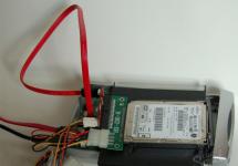
First, you need to find a flat surface and carefully place the system unit so that the left cover is facing you, while you should not disconnect all the wires in order to complete everything faster, but you should make sure that these wires are not strained. In addition, a prerequisite must be that the computer is disconnected from the power supply, as they say, you never know. Next, what needs to be done is to remove the left housing cover. In modern cases, this usually does not require any great effort, so this should not be a problem.
After removing the cover, a stunning picture will appear in front of you. You will see everything that at one time you paid a round sum for, and that usually works peacefully, making an innocent noise, and that which now does not want to “start up”. Our attention should be primarily focused on the multi-colored wires that run from the front of the case to the motherboard. There can be a lot of such wiring, and it’s not surprising, because there are also connected POWER buttons And RESET button, and USB ports, along with audio outputs. So, at the next step, we may need a little knowledge of English, which many received at school, because on the wiring themselves, as well as on the motherboard, near the connection of these wiring, it should be written what they mean. For example, you can take USB ports. On the motherboard itself, near the connection, there should be an inscription USB1, USB2, etc. This means that the wires connected to these connectors are nothing more than USB connection ports.
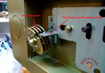
But we shouldn’t forget about our problem, and this means that we need to look for POWER postings(usually these are two wires woven together). Typically, the connectors to which the power or reset buttons are connected are located on the lower right side of the motherboard:
On most motherboards, these connectors are the same and consist of 9 pins arranged in two rows. The last two pins in a short row of 4 plugs are responsible for turning the computer on/off.
Here are connector diagrams for the most popular motherboard manufacturers.
MSI
AsRock
Asus
Biostar
Epox
Foxconn
Gigabyte
Intel
Once these two wires have been found, you should find where they are connected to the motherboard. Once the connection location has been discovered, it is worth carefully disconnecting these wires so that the small plugs are exposed.
That's it, now we're almost done. The final step is to turn on the computer; for this we need an ordinary stationery pen, preferably one that writes boldly. Once you have found such a pen, you can connect your computer to the power supply, and then carefully run the tip of the rod over these exposed needles. Or in other words, you just need to close these contacts. After these steps, the computer should come to life and the download will begin. If nothing happens, then you should repeat the procedure, but close these needles quickly enough.
Thanks to these simple steps, you can start the computer without any problems, but this should not be neglected, and it is better to quickly repair the start button on the case to avoid unnecessary problems.
Attention: Neither the author of this article nor the administration of this site bears any responsibility for possible problems that may arise when turning on the computer in this way. You will perform all of the above actions at your own peril and risk, and will be solely responsible for possible problems that are not described in this article.
The motherboard is the basis of any computer. It determines what components can be connected to it, and therefore what the machine will be capable of. All connections are easy to make yourself if you know what and how to do.
The first thing you need to do is connect the power supply. As the name suggests, it will supply electricity to all components. The following connectors come from it:- 24-pin (less often - 20) to the motherboard with various “lines” for 3, 5 and 12 V;
- 4-pin 12 V;
- sata and molex;
- drive power supply.


As we saw from the article, there is nothing complicated about connecting wires to the motherboard. This process can be performed by any user by simply connecting the desired connector to a slot of a suitable shape. The main thing is not to rush and make all connections without using force, so that the equipment remains in working order.
How do I connect the motherboard to the front panel, which contains all the main buttons and indicators?
Attaching the motherboard to the front panel is a standard computer assembly process.
Before starting the connection process, you should study in detail the appearance of each element of the front panel of the computer case and the queue of its connection to the motherboard.
Remember! If you connect items to the main system board in the wrong order, some of them may not work or may not function correctly.
It is quite simple to study the names of all elements and their location. All of them have a certain marking, name and appearance.
Connecting all buttons and status indicators
Any case contains computer status indicators, LEDs, buttons, and disk drives. Other elements may also be present.
On the computer motherboard there is a separate block for connecting diode bulbs (indicating the power-on status) and buttons.
The components are connected to this block using four separate connectors.
Their appearance is shown in the figure below. They look the same on all computers, but the phrases written on them may differ (but they mean the same thing).
The connectors are painted in different colors.
Yellow is for connecting the power button, blue is for the system status diode (lit when the system is rebooted).
The green connector connects the power button indicator lamp to the computer motherboard (after pressing the power key, the corresponding lamp lights up green).
Red – power button cable.
The connector that connects the speaker to the housing can also be painted yellow.
This speaker makes a beeping sound when you turn on your computer, detect system errors, or connect to a wireless network.
All connectors connect to one specific port on the motherboard. Typically, such a port is located at the bottom right of the system's main board.
Manufacturers of computer parts call this port the word PANEL and its variations (F_PANEL).
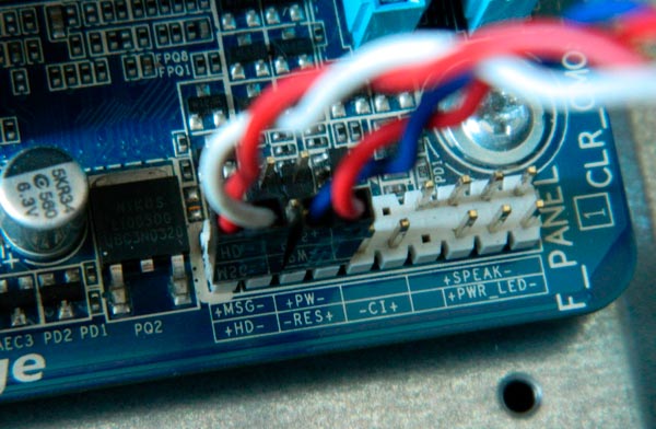
Absolutely every motherboard has signatures that indicate what needs to be connected and where. The figure below shows the required port on the board.
The arrows indicate where each connector should be connected.

On the main board you can often find a separate connector for connecting a speaker, which responds to errors in the BIOS and in the computer hardware.
The location of the connector is shown in the figure:

After connecting the block with buttons and diodes, you can begin connecting all the front USB inputs, as well as audio outputs.
The process of connecting the front panel of the system unit case
The appearance of the connectors for USB and audio is practically no different from those connectors that were described above in the article.
However, unlike the previous connector wires, they are connected together.
Each connector has a name (USB and HD AUDIO, respectively). The appearance of the wires is shown in the figure below:

The connector for connecting these connectors on the motherboard is located in its lower part and, as a rule, is labeled F_USB1 or F_USB2.
There may be more than two connectors for connection (newer versions of motherboards).
It doesn't matter where you connect which wire.
All inputs are absolutely identical; the order in which they are connected does not in any way affect the operation of the components on the front panel of the computer.
It is also impossible to make a mistake with the correct side of the connector.
The USB connector can only be connected on one side.
Follow the instructions:
- Find the connector named F_USB;
- Locate the corresponding connectors on the motherboard. Their location is indicated in the figure;

- Connect the connectors to any of the connectors on the board.
Note! If your computer case indicates that the USB 3.0 version is used, you must connect the connector only to a specific connector. Which one you can read in the instructions that came with the motherboard.
Connecting the Front Soundbar to the Main Board
Now you need to connect the audio devices to the motherboard. All actions are almost the same as how USB connectors are connected.
The connectors are also connected together with each other.
This way you can connect all components to the computer motherboard without errors.
On most motherboards, all audio connectors are located near the USB connectors. The approximate location of the ports can be seen in the figure below:

Most often, sound connectors are labeled AC 97.
When replacing the motherboard or computer assembly, the user quite often encounters the problem of connecting the front panel of the system unit. Perhaps this is the only moment that causes certain difficulties. The best option is when you have a manual or connection diagram on hand. This information can be found through the official website and download this manual for the board.
As a rule, the connection of controls and connectors of the front panel of the case begins when the motherboard is already fixed in the case. The controls are a bundle of wires with connectors Power LED- and Power LED+ (computer status indicator), Power SW (power key), Reset SW (forced reboot button) and HDD LED-, HDD LED+ (drive activity indicator). All motherboard manufacturers use their own designations. For example, PANEL in ASUS, F_PANEL in GIGABYTE, JFP1 in MSI boards; PANEL1 in ASRock.
The approximate diagram of connecting the front panel to the motherboard is as follows, but depending on the manufacturer it may differ slightly.
| Power LED- | Power SW | Power SW | |
| HDD LED+ | HDD LED- | Reset SW |
Each cable has its own port. If the connection is incorrect, the computer simply will not start. This is what the place to connect the main elements looks like. Below there is a table from which you can determine in what order you need to connect the wires. There are two rows of pins for power, so all connections must be exactly as shown in the table.

The same connection diagram is in the manual for the motherboard, but it is often not entirely clear how to connect due to the lack of step-by-step photographs.
To connect the front audio connectors, you need to stretch the corresponding wire labeled Audio to the opposite end of the motherboard. There should be an inscription with a designation. Nearby is a connector for connecting the system unit fan, which is responsible for the removal of warm air and circulation when the case is closed.

A little to the right are connectors for connecting the front USB ports. Agree, it’s not very convenient when they don’t work, and in order to quickly connect a memory card you have to crawl under the table to the system unit. There is a corresponding inscription on the wire that cannot be confused in any way. In this case, it is a blue wire.

The next step is to connect the wires labeled HDD LED, Power SW, Reset SW and Speaker. Each of them has its own function, so it is impossible to exclude any of them. The first wire on the list is responsible for indicating the operation of the hard drive. A very important parameter, since all computer data is stored on it.

Next, next to it in the bottom row, the wire responsible for restarting the computer is connected. If it is not connected, the small button on the front panel of the system unit will not work and there will be no way to restart the computer in emergency mode.
Above it are the contacts responsible for starting the computer. If you close these two contacts with a regular screwdriver, the computer will turn on itself.

In the upper right part you need to connect the Speaker wire, which is responsible for all the signals that the computer emits at startup. By these sounds you can determine all the problems associated with the computer hardware. This is what the motherboard panel should look like with all the wires connected.

If everything is done correctly, then you can now safely use the elements that are located on the front of the system unit, turn on and restart the computer.
Few novice users decide to implement the process of assembling a computer system with their own hands. Nevertheless, this “purchase option” is considered to be the most profitable. Since the user himself decides what exactly the hardware configuration of his computing device should be. At the same time, the correct connection of the front panel to the motherboard is a very important point in the overall assembly process. Some intricacy of the mentioned operation requires knowledge and precise actions from the practitioner. However, more details about everything in the following article.
Instead of introduction: claws, plugs and plug connectors
After you have installed the central processor, positioned and secured the main element of its cooling - the cooler, inserted RAM strips into special slots and equipped the motherboard with a hard drive (in general, installed important PC components), the moment comes when you need to connect the front panels to the motherboard. However, for many novice users, the last operation sometimes becomes simply impossible. After all, the system unit often has a bunch of incomprehensible wires. In some cases, their “quantity” is striking in its diversity and mystery of purpose. Since the case manufacturer does not always adhere to generally accepted standards, changing the cable markings and their location. However, everything can be easily resolved if the user carefully studies the technical documentation for the purchased device and strictly follows the installation instructions described below.
Trigger elements and indications
So, before carrying out the direct process - connecting the front panel to the motherboard, you need to conduct a visual inspection of the main system part for an accumulation of plug-type contacts. In other words, you need to find out where the connector pad is located through which the computer starts. After all, most motherboards, in addition to the main startup/shutdown and reboot unit, have in their, so to speak, configuration arsenal a number of additional connectors, which will also be discussed within the framework of this article.

- When connecting the front panel to an Asus motherboard (the brand is indicated as an example), locate the connector pad labeled “Front panel.”
- Focus on the color coding of the contact pads and their designation.
- The two-pin “Power SW” wire must fit into the corresponding socket, as well as the other control cables: “Reset SW”, “HDD LED” and “Power LED”. By the way, when connecting the last group of contacts, it is necessary to observe the polarity (there are “+” and “-” signs on the board).
- The “Speaker” sound sensor is also connected according to the principle described above.
Important digression
If for any reason you reverse the polarity or incorrectly position the mentioned controls, the computer may not start at all, or there will be no light indication of the operating equipment.

Therefore, be extremely careful when connecting the front panel to the motherboard. However, don't worry too much if something goes wrong. You can always correct a connection error by moving the incorrectly connected wires to a position that corresponds to the working diagram.
Additional interface connectors
Modern system units, in addition to the “Power” and “Reset” buttons located on the front of the case, are often equipped with additional Audio and USB ports. In some cases, there may be a card reader (a device for reading/writing memory cards) and even an IEEE 1394 connector, through which various peripheral devices can be connected. In any case, to improve the comfort of working on a PC, additional interface connectors must be activated. That is, first of all, they need to be physically connected to the motherboard and, if necessary, make some changes to the BIOS firmware parameters. However, let's not get ahead of ourselves...
Front Panel USB Connection

The motherboard (when you purchase it directly from the store) is always accompanied by a technical data sheet, which indicates the location of a specific connector and its purpose. At the same time, in the documentation the user can always find a graphically displayed connection diagram for the required device.
- Locate the pin connector labeled USB on the system board. You'll likely find several of them. By the way, in multifunctional modifications of computers there can be up to ten such ports.
- Connect the connector coming from the front panel to the nine-pin socket.
- Make sure that the joints of the plastic parts fit tightly together.
In the case when the USB connector connected to the board does not have an integral structure, for example, it has a limit switch branched into four pins, use the following instructions.
Resolving a difficult situation: USB “pinout”

As a rule, each of the four pins has its own designation in the form of an inscription:
- “VCC” is the wire that receives +5 Volt power.
- “Data -” or “D -” is negative data.
- “Data +” or abbreviated “D +” is the opposite of the previous point.
- "GND" - ground (mass).
When the user connects the front panel connectors to the motherboard, he must remember that if the “pinout” is incorrectly used, there is a risk of damaging any system component. As you understand, haste and rash actions can cost you dearly. Therefore, connect each wire to a strictly defined location on the mother connector.
- "VCC" is the first one.
- Then, “Data -”.
- The third pin is “Data +”.
- The last one is "GND".
By the way, after the “ground” there remains an unoccupied pin of the first port; the lower row of connectors is connected according to the instructions described above. However, there will no longer be an “extra” pin after the mass. As you can see, everything is simple!

Agree, it’s convenient when there is a microphone input jack and an Audio output for headphones on the front side of the PC case. However, despite the simplicity of immediately connecting an additional audio panel to the motherboard of your PC, the user is often faced with an incomprehensible effect - the connectors do not work properly or do not function at all. To avoid such an unpleasant situation or to understand the true reasons for “digital silence”, you need to do the following:
- Make sure the front audio panel matches your motherboard's audio standard and is connected to the appropriate "F-AUDIO" connector.
For example, if your motherboard supports “HD Audio”, then most likely this mode is activated by default, which means that the external “AC’97” module will not work. If the stipulated condition can be corrected by reconfiguring some software components, then if we consider the above situation in the context of the opposite, it will be necessary to completely replace the external audio module. The fact is that the “HD Audio” standard uses different codecs than “AC’97” and is incompatible in use with the latter due to some technical differences.
How to enable front panel connection in BIOS?
Just enter the BIOS firmware and find the corresponding audio device settings section. As a rule, you can make the necessary changes by using the “Advanced” tab, and by going to the “Front panel select” parameter change checkbox, set the desired working value. It is worth noting that a particular computer manufacturer equips its devices with the original version of the basic system. Therefore, some names of the BSVV control interface items may be designated differently.
Changes to settings in Sound Manager
Sometimes this happens: despite the front panel being correctly (physically) connected to the Gigabyte motherboard, the audio devices connected to the front connectors do not work.

The sound "snag" is resolved as follows:
- Go to Realtek HD Manager and enable the Disable Front Panel Jack Detection option.
- It may be that in the main “Connector Parameters” settings you need to enable the “item” that corresponds to the sound standard of the external audio module.
Finally
So, if you, dear reader, have a diagram for connecting the front panel to the motherboard (and this is not difficult to find out by looking at the technical documentation of your device), then a positive result is guaranteed. Remember that an incorrectly used connector can cause total breakdown of your computer. That's it - rational decisions and full-fledged achievements for you!