For people who like to design electronic devices, sooner or later the need arises to use microcontrollers in their developments. The use of these devices opens up enormous opportunities for the radio engineer. Microcontrollers are produced by only a few companies; the leaders are Microchip Technology, ATMEL, ARM Limited. A feature of such devices is the need for their firmware. This is what programmers are for. There are many types of these devices, you can buy a branded one, or you can make it yourself. If you choose the second option, it is best to use a ready-made and proven solution, such as the Gromov programmer. The device is quite simple, even a beginner can assemble it.
COM(AVR)-programmer Gromov
The COM programmer is easy to manufacture. Provided that the alternative mode of the “COM” Bitbang port is used, conversion to SPI, which is necessary for programming, becomes unnecessary. All that remains is to coordinate the signal levels in the COM port, from -12V, +12V to 0V and +5V. This is what the programmer circuit for AVR controllers is designed for. The photo below shows Gromov's programmer.
In order to begin assembling the device, we will need:

As you can see, everything is very simple, this is why Gromov’s programmer is valuable.
To operate this device, you need a program and test firmware of the microcontroller.

Using the same principle, you can assemble a usb programmer, but the circuit of such a device is somewhat more complicated.
Just as a theater begins with a hanger, so programming microcontrollers begins with choosing a good programmer. Since I’m starting to master microcontrollers from ATMEL, I had to thoroughly familiarize myself with what the manufacturers offer. They offer a lot of interesting and tasty things, only at exorbitant prices. For example, a scarf with one twenty-legged microcontroller with a pair of resistors and diodes as a harness costs like an “airplane”. Therefore, the question of self-assembly of the programmer arose. After a long study of the developments of experienced radio amateurs, it was decided to assemble a well-proven USBASP programmer, the brain of which is the Atmega8 microcontroller (there are also firmware options for atmega88 and atmega48). The minimal wiring of the microcontroller allows you to assemble a fairly miniature programmer that you can always take with you, like a flash drive.
The author of this programmer is the German Thomas Fichl, his development page with diagrams, printed circuit board files and drivers.
Once it was decided to assemble a miniature programmer, I redrew the circuit for the Atmega8 microcontroller in the TQFP32 package (the pinout of the microcontroller differs from the pinout in the DIP package):
Jumper J1 is used if it is necessary to flash a microcontroller with a clock frequency below 1.5 MHz. By the way, this jumper can be eliminated altogether by placing the 25th leg of the MK on the ground. Then the programmer will always operate at a reduced frequency. Personally, I noticed that programming at a reduced speed takes a fraction of a second longer, and therefore now I don’t pull the jumper, but constantly sew with it.
Zener diodes D1 and D2 are used to match the levels between the programmer and the USB bus; it will work without them, but not on all computers.
The blue LED indicates that the circuit is ready to be programmed; the red LED lights up during programming. The programming contacts are located on the IDC-06 connector, the pinout complies with the ATMEL standard for a 6-pin ISP connector:

This connector contains contacts for powering programmable devices; here it is taken directly from the computer’s USB port, so you need to be careful and avoid short circuits. The same connector is also used for programming the control microcontroller; to do this, just connect the Reset pins on the connector and on the microcontroller (see the red dotted line in the diagram). In the author's circuit, this is done with a jumper, but I did not clutter the board and removed it. For a single firmware, a simple wire jumper will suffice. The board turned out to be double-sided, measuring 45x18 mm.

The programming connector and a jumper to reduce the speed of the programmer are located at the end of the device, this is very convenient

Firmware of the control microcontroller
So, after assembling the device, the most important thing left is to flash the control microcontroller. Friends who still have computers with an LPT port are well suited for these purposes :) The simplest five-wire programmer for AVRThe microcontroller can be flashed from the programming connector by connecting the Reset pins of the microcontroller (29 leg) and the connector. Firmware exists for Atmega48, Atmega8 and Atmega88 models. It is advisable to use one of the last two stones, since support for the Atmega48 version has been discontinued and the latest firmware version dates back to 2009. And versions for the 8th and 88th stones are constantly updated, and the author seems to be planning to add an in-circuit debugger to the functionality. We get the firmware from the German page. To upload the control program to the microcontroller, I used the PonyProg program. When programming, it is necessary to set the crystal to work from an external clock source at 12 MHz. Screenshot of the program with fuse jumper settings in PonyProg:

After flashing the firmware, the LED connected to leg 23 of the microcontroller should light up. This will be a sure sign that the programmer has been successfully programmed and is ready for use.
Driver installation
The installation was carried out on a machine with Windows 7 and no problems arose. When you connect to your computer for the first time, a message will appear indicating that a new device has been detected, prompting you to install a driver. Select installation from the specified location:

A window will instantly appear with a warning that the driver being installed does not have a digital signature for small soft ones:

We ignore the warning and continue the installation, after a short pause a window will appear informing us that the driver installation operation has been successfully completed

That's it, the programmer is now ready for use.
Khazama AVR Programmer
To work with the programmer, I chose the Khazama AVR Programmer flasher. A wonderful program with a minimalistic interface.
It works with all popular AVR microcontrollers, allows you to flash flash and eeprom, view the contents of memory, erase the chip, and also change the configuration of fuse bits. In general, a completely standard set. The fuse setting is carried out by selecting the clock source from the drop-down list, thus the likelihood of locking the crystal by mistake is sharply reduced. Fuses can also be changed by placing checkboxes in the lower field, but you cannot place checkboxes on a non-existent configuration, and this is also a big plus in terms of security.

Fuses are written to the MK memory, as you might guess, by pressing the Write All button. The Save button saves the current configuration, and the Load button returns the saved one. True, I could not come up with a practical use for these buttons. The Default button is designed to record the standard fuse configuration, the one with which microcontrollers come from the factory (usually 1 MHz from the internal RC).
In general, during all the time I have been using this programmer, it has shown itself to be the best in terms of stability and speed of operation. It worked without problems both on an ancient desktop PC and on a new laptop.
You can download the PCB file in SprintLayout using
The first question you want to ask head-on is what exactly is “programmer”? The word “programmer” is formed, oddly enough, from the word “program”. What is a program? If you remember what it is body program and why it was needed (by the way, it is still sold in kiosks), then it becomes clear that a TV program is time schedule these same TV shows. This means that a program can be called some actions or events that will be performed one after another in time, when we want it or not. Hence, programmer- this is just some kind of device that allows us write down or read program. Change the program can only be done by himself programmer;-)
CM
For novice radio amateurs, the transition from assembling simple analog devices, such as multivibrators, to assembling devices using MK can be difficult because it is not enough to simply wire and solder the device on a printed circuit board, you also need to upload the firmware into the microcontroller memory using programmer. As has already been written in previous articles, a microcontroller, until we have “uploaded” the firmware into it, is simply a useless piece of silicon. And then a novice radio amateur is looking for information on the Internet about assembling a simple but effective programmer that would help him get a quick start in this difficult task.
I will not be mistaken if I say that 80% of beginners, if they have a COM port on their computer, assemble . This scheme, with its simplicity and skillful handling, is a real masterpiece). Indeed, in order to assemble a programmer with your own hands, connected to a USB port and containing an AVR microcontroller, which must be pre-programmed, you again need a programmer. Where can a beginner get a programmer, even for such a one-time firmware? It turns out to be a chicken and egg paradox), in order to assemble a USB programmer, we first need to program the microcontroller of the programmer))).
So, let's look at what exactly is flashing a microcontroller (MK) using a programmer, and how is it done? In order to flash the MK, we need a combination of the programmer itself, a device soldered on a printed circuit board, and a program called shell, working with this device.
Each type of programmer most often requires its own shell. To assemble the Gromov programmer, you do not need to program the microcontroller. This programmer does not have it. This programmer works with two widely used flashing shells: PonyProg And Uniprof. We will have separate reviews of these programs. This programmer connects to COM port. The only obstacle to its assembly may be the physical absence of this connector on the motherboard of your system unit. Why the system unit? Because laptops, as well as modern models of motherboards produced in 2010–2011 and higher, often have a reduced supply voltage on the COM port contacts. What does this mean? This means that you can assemble this programmer, but it will not work for you. But with computers manufactured in 2007–2008 and older, with the exception of laptops, this programmer should be guaranteed to work. Connecting via USB - COM adapters does not help in this case, since at best there is a strong decrease in speed, and at worst, the programmer refuses to work at all.
Let's look at the circuit diagram of the programmer:

What do we see in this diagram? COM port connector, otherwise called DB9, 7 resistors of the same value with a resistance of 1 kOhm and a power of 0.25 Watt and 3 pulse diodes. The suitable diodes are either domestic ones, KD522, KD510, or imported 1N4148.
Let's look at what these radio components look like.
The photo below shows the DB9 connector:

As we can see, the pins (terminals) of this connector are indicated by numbers on it. If there are any difficulties in determining which pin corresponds to which hole of the connector, I recommend inserting a wire into the pin hole of the connector, switching to audible testing mode and simultaneously touching the wire with the multimeter probes to each of the pins on the connector in turn, and checking the correspondence of the pins to the holes. This may be required if you are connecting the connector with wires to the board. If the connector is soldered directly to the board, then these steps are not required.
Those who do not have a COM connector on the motherboard connector panel located at the back of the computer can buy brackets with such a connector. But you need to make sure that the manufacturers have soldered the COM port controller to the motherboard, and provided for connecting the cable of this strip directly to the board. Otherwise, this option will not help you. As an alternative, I can suggest purchasing a COM port controller located on a special expansion card, which is installed in the PCI slot of the PC

Also, if you wish, if you want the cable connected to the COM port to be disconnected from the programmer, you can unscrew the fastening screws, remove the connector from the bracket, and secure it in the programmer body. But be careful, and after purchasing, ring all the wires to match the numbers on both ends of the cable, because cables that are similar in appearance and have crossed wires are often on sale. The cable for connecting to this connector must be fully wired, DB9F - DB9F, straight, not crossed, the connector will not work with other cables.

If you have problems purchasing this cable, you can take a crossed cable or a 9M-9F extension cable, but in this case you may need to cut the connector at the other end and solder the wires along the pins of the connector directly to the programmer board. By the way, I had just such an extension cable, and I had to cut the connector from the second end. Do not buy cables for flashing phones via the COM port; they are not suitable for our purposes, since the wiring is incomplete.
We take KD522, KD510 or 1N4148 diodes. This is what the KD522 diode looks like

Be careful, the diode has a switching polarity. In other words, it doesn’t matter how you solder it, you can solder it backwards, then the programmer will not work. As you know, a diode has a cathode and an anode. The cathode is marked, in this case, with a black ring.
Well, I think there will be no problems. Go to a radio store and tell the seller: “I need 1 kOhm 0.25 Watt resistors.” It is advisable to take imported resistors, since domestic MLTs have a greater deviation from the nominal value.

If you know the method, then it will not be difficult for you to assemble a programmer using this printed circuit board. Below is a screenshot of the board from the Sprint Layout program:

If you have not yet mastered the LUT method, then the following board will be more suitable for you, the design of which can be easily drawn with a PCB marker directly on the PCB. You can download both versions of printed circuit boards in the general archive at the end of the article. Don't forget to clean and degrease the board before applying the design. The pins of the parts on it are not located close, and even beginners will not have problems with soldering

The board differs from the original circuit in the presence of an indication LED and a current-limiting resistor in the LED circuit. All pins are labeled on the board. On the left are the numbers of the COM port cable pins that need to be soldered to the board; unsigned core numbers can be insulated and not soldered. On the right are pins for connecting to a programmable microcontroller.
I assembled this programmer five years ago on a board made from a marker. This is what its printed circuit board looked like after tinning at the assembly stage in the case:

Sorry for the blue electrical tape)), back then, 5 years ago, heat-shrinkable tubing was a novelty.
The programmer cable connector at the other end was cut off, and the cable wires were soldered directly into the board. The cable itself was secured with a metal clamp. The photo shows that the cable is thick, and if it were not secured, bending could disrupt the contact of the wires on the programmer board

To connect to the microcontroller installed for flashing on a solderless breadboard, I used colored flexible wires. Connected with wires of the same color, taken from the twisted pair wires. This is done so that, on the one hand, the wires do not break during operation, and on the other, easy connection to the breadboard is ensured. The length of these wires should be a maximum of 20 - 25 cm, in order to avoid errors from interference during programming. Do not use ordinary unshielded wires instead of a COM cable! You will be tormented by errors when installing the firmware.
The programmable microcontroller requires an external +5 Volt power supply supplied to the programmer. For this purpose, you can assemble a stabilizer on a 7805 chip, powered by an external power supply, or do it simpler and use a cable and a charger with a USB output, soldering the wires of the USB cable directly to the printed circuit board.
For reference: power and ground in the USB connector go along the edges. Here is the pinout of the USB connector:


Theoretically, if you are a fairly careful person, you can also get power from the USB port of your computer by connecting this cable to it, but remember, you do this at your own peril and risk! It’s better to find money once and buy a USB charger. Do not use non-USB, unstabilized chargers for cell phones and other equipment; you risk damaging the microcontroller.
When powered from the computer's USB port, if the wires of the programmer +5 volts (VCC) and ground (GND) are shorted, you risk burning the south bridge of the computer's motherboard; repairing such a motherboard will be impractical. I used both options to supply power, both through the stabilizer and through the cable from the USB charger. One more nuance, after programming the microcontroller, in order for the microcontroller to start, it is necessary to break the RESET circuit.
This can be done simply by unplugging the wire connected to the RESET pin of the programmer. And then the program embedded in the microcontroller will begin to execute. I decided to make a more convenient solution and installed a small-sized key switch to break the RESET circuit.

In other words, when it is turned off, the current no longer flows in this circuit and the microcontroller starts working. Instead of a key switch, you can use any small-sized button with a lock, or install a toggle switch. Whose imagination can tell you what ;-)
Surely you have already noticed that on the diagram of Gromov’s programmer there are some unfamiliar words, and in particular VCC, GND, MISO, MOSI, SCK and RESET. Let's look at what these designations mean using the Attiny 2313 microcontroller as an example.

In this case, a very common and inexpensive microcircuit is shown: the AVR Tiny microcontroller (aka Attiny) 2313. The legs of the microcircuit, as we can see, have their own number. The numbering goes counterclockwise, from the key in the form of a dot located in the upper left corner of the microcontroller case. Below is an example of how the numbering works on microcircuits in a DIP package:


We are primarily interested in the six legs listed above. We will briefly touch on the purposes of all the others at the end of the article.
So, let's decipher:
VCC. We supply the supply voltage to the microcircuit to this leg. The standard is 5 Volts. An upward deviation is permissible, up to 5.5 Volts. Voltage above 6 Volts can damage the microcircuit. A smaller deviation is more acceptable. There are versions of Tiny 2313V microcontrollers that can even operate from two AA batteries or rechargeable batteries, or from a voltage of 2.4 Volts.
GND. Well, this is the familiar and well-known “ground”, it is also “mass”, and it is also the minus of power. This contact is common to all devices that are connected to each other. If you connect any device blocks to each other, their lands should be combined. In this case, the microcontroller ground is combined with the programmer ground.
MISO. Abbreviation for M aster – I n – S love - O ut. This line transmits data from the microcontroller to the programmer.
MOSI. Abbreviation for M aster – O ut – S love - I n. This line also transmits data from the programmer to the microcontroller.
SCK. A clock signal is generated on this line.
RESET. This pin is used to reset the microcontroller after erasing with a single pulse. If RESET is disabled by mistakenly setting a certain fuse (we will talk about setting this and other fuses in the following articles), we will not be able to erase and reflash the microcontroller via the SPI interface.
It is enough to connect these listed 6 pins of the programmer to the 6 legs of the microcontroller, and we can flash the MK.
Let's look at the rest of the MK legs:
The Tiny2313 microcontroller has 3 ports: A (A0-A2, 3 legs), B (B0-B7, 8 legs) D (D0-D6, 7 legs), in total there are 18 input/output ports used as legs. Each of these pins can be configured separately as input and output. They are not port pins, only ground (GND) and power (VCC).
The additional purpose of some MK legs is discussed below:
OC1A And OC1B. Legs for generating PWM (Pulse Width Modulation) signal, timer 1.
OC0A and OC0B. Legs for generating a PWM signal, timer 0.
AIN0 and AIN1. Legs for supplying an analog signal to the microcontroller.
XTAL1 and XTAL2. Legs for connecting a quartz resonator for clocking from it.
RXD and TXD. MK connection lines via UART interface.
I hope this article will be useful to novice microcontroller enthusiasts, and will allow you to build a programmer that will delight you with its work for a long time.
Hi all. Today I have a new article for you, dedicated to one of the simplest and most popular AVRok programmers - the Gromov programmer - as it is called on the network.
I had been planning this article about the programmer for a long time, but somehow there was no time for it. But now let's get started.
There are two ways to program the AVR controller today:
1) Using a high voltage parallel programmer. This is more of an industrial option, since in this case the controller body is placed in a special socket and a pre-prepared program is sewn in by applying high voltage (higher than the supply voltage). After which the controller is soldered into the board at its destination. There is a tangible advantage here - complete control over the entire inside of the controller. And the sewing process is instant.
But what if it turns out that the hardwired program has an unforgivable bug? So what should you do - the controller is already soldered? Desolder again?
This option is not suitable for amateur radio practice, although it will be useful to have a high-voltage programmer in your stash. By the way, one of the following articles will contain very useful information, so do not miss.
2) We will take a different path - and we have an in-circuit programmer at our service. With this method, the controller is installed immediately into the circuit without any intermediate steps. In this case, the program is stitched in-circuit. What does this mean?
It's simple, when developing any device, we provide a programming connector in advance. We install the programming connector directly on the board of our device. This is exactly what I did, there is a connector there, and the connector can be anything, but there is a certain standard for this matter. Typically a ten-pin PLS connector is used, similar to those found on computer motherboards.

So, 5 signals are output to this connector from the controller: mosi, miso, sck, reset, GND. The program will be stitched through these contacts. Moreover, we can do this many times—after all, we don’t have to solder anything. The only thing that needs to be done is that the controller needs to be powered up and running. However, power can also be supplied from the programming connector. Then we will no longer have five signals, but six, but this is not at all difficult. Only here there is a small peculiarity - you need to be careful when placing fuses ( FUSE) before installing the program. If during high-voltage programming an incorrectly wired fuse bit is easily corrected, then during in-circuit programming it will be difficult to correct anything.
A small digression.
Fuses or fuse bits are controller configuration bits. They cannot be removed from the body of the program. Fuse bits are usually set before flashing the program - using a programmer and a flashing program.
Using fuse bits you can change the way the controller clocks. So, if in your circuit the controller is clocked from its internal oscillator, and you set the clocking method from quartz in the fuses, then the circuit will not work. The controller will not start, which means that nothing can be changed. But this is a fixable matter. You just need to solder the required quartz and a couple of capacitors, then everything will work and the program can be further edited and modified.
But there is a fuse bit, by setting which we lose the possibility of in-circuit programming - we need a parallel programmer. So be careful and read the datasheet thoroughly before sewing up fuse bits.
Today there are very, very many varieties of in-circuit programmers, and choosing an acceptable option is not easy. All programmers are divided according to the method of connection to the computer; I know of three: via LPT, COM, USB.
I do not recommend a programmer working through the lpt port in advance, since it is very easy to burn it, and no matter how many circuit solutions were advised to me, I immediately discarded this option. By the way, yes, the lpt port itself was not on my work machine. That's it.
Nowadays, when com and lpt ports are becoming obsolete, the only working option is USB. But there are a number of problems here. As a rule, programmer circuits powered by USB include a microcontroller, which naturally needs to be flashed, and for flashing you need a programmer. This is such a vicious circle. Although recently a USB programmer circuit has appeared on the Internet, which does not require firmware. The scheme is simple, but I haven’t thoroughly understood it, so I won’t talk about it - if you find it very interesting yourself.
We will take a more complicated path - we will start manufacturing the Gromov programmer. This programmer works through a com port, which, unlike lpt, is rare but still found in modern computers. And by the way, if you don’t find it on the back wall of your computer, this does not mean that it doesn’t exist, since on many motherboards it can be present in the form of pins, pls, you need to read the documentation for the motherboard.
Scheme.
The circuitry of the programmer itself is surprisingly simple and I am very sorry that I have not seen it before.

It can even be assembled by hanging it on a knee, but it will still look more solid on the board. For this programmer we need seven resistors of a kilo-ohm each and three low-power diodes. As you know, the voltage from the com port is within 12 V, and the controller operates with a 5-volt voltage. So, a circuit of diodes and resistors will serve us to match the levels. A resistor divider of 12 volts gives us 6 volts, and the remainder of one volt is deposited on the diode - we get 5 volts and this is what we need.
I drew the diagram in the Eagle CAD program, then with a few simple mouse movements, this scarf was born.

You can download the project files from this link.
Her drawing was printed on a laser printer and subjected to brutal brutality. After all the manipulations, all I had to do was solder the parts and present this creation to your judgment. 🙂


Entrances and exits.
On the left side of the board there are mounting holes for connecting a DB-9F (female) connector known as a COM port connector. it will be connected to our board via wires. The holes for this are indicated on the diagram: DB9/2, DB9/3, DB9/4, DB9/5, DB9/7, DB9/8. The contacts are labeled on the diagram - you won’t miss it :) I would like to add that it is advisable to take the wire no longer than 25 cm. With a longer wire, interference may occur, and as a result, errors when installing the program.
In my version, the power will be supplied from the computer, so for convenience I have displayed the contacts

power supplies PinGND and Pin+5. Then they will be connected to the power connector; in principle, a separate power supply with a voltage of +5 V can be used for this purpose - there will be no problem.
For myself, I saved this connector from an old computer. We solder +5 V to the extreme red wire, and the ground is soldered to the black one. The rest can be bitten out so it doesn't get in the way.
On the right side there are contacts for soldering the ten-pin programming IDC connector. For me it looks like this. Here it comes in conjunction with a DB-9M connector (male).

This entire structure is connected to the programmer board via a DB-9F connector.

Now you can sit back and relax, because we can say that we have completed the task - we have assembled Gromov’s programmer. But we cannot relax for long, because the tests of our creation lie ahead of us. Therefore, in order not to surprise your computer, I advise you to carefully ring everything with a multimeter and check the installation, and only after that proceed to testing our device.
So we have the programmer assembled and lying on the table, waiting. In order to bring to life everything that we have planned, we need control software - the Uniprof Program.
Uniprof program - This is the same software with which our programmer will communicate with the computer. This program was written by an author named Nikolaev, for which an entire army of radio amateurs says to him - THANK YOU. By the way, the program itself can be downloaded from author's website or I have.
We turn off our computer and connect the programmer using a DB-9F connector to the COM port of the computer. I connected the power connector to the power supply of my native computer. At this stage, it is advisable to connect the board of our programmable patient - a board with a controller. I connected an experimental board with an Attiny 45 controller. Well, now a minute of silence. . . Press the POWER button of the computer system unit. We are waiting for our operating system to load.
Let's launch Uniprof. When starting, it cursed a little, displaying a window with the familiar ERROR, saying that there was something wrong with my LPT. . . heh, it’s a bit stupid, of course, but we’ll forgive him this time by pointing him on the cross.

At the next stage, the program window did open, but a message appeared stating that the controller did not respond. But we don't panic.

After all, the program is not at all aware of which port our controller is connected to. Here, in addition to the previously mentioned LPT port, there is also a set from COM1 to COM5 to choose from. So by simple search we achieve full identification of our controller.

The controller has been determined, now we need to read it - click on READ.
If the controller is clean, then there should be dashes in the program window, but in my case it turned out differently - the dashes alternated with various hexadecimal numbers. Perhaps the problem was in the long wire connecting the programmer to the computer or to the high performance computer. But in any case, this was cured by checking the “BRAKE” checkbox. The reading time turned out to be slightly longer, but the result was better.

Now it’s time to write the HEX program file to our controller, but we also need to remember to set the correct fuse bits. They are accessed by pressing the button labeled FUSE.

We set everything correctly, having previously studied the datasheet for the desired controller. Important advice: read the fuses and make sure that the fuse bit SPIEN is not set, since setting this fuse will not allow you to use our Gromov programmer for this controller in the future.
Next, click on the button with an open yellow folder called HEX and select our HEX. 🙂 The program text should be reflected in the Uniprof window. Well, now all that remains is to click on the button with the red arrow called Prog and it’s done.
As you can see, programming the controller using this program is not at all difficult. To become more familiar with it, I recommend reading the help, there you will find answers to your questions.
By the way, read about it, which I soldered and programmed. To do this, the programmer came in handy.
Dear friends, recently a very convenient way to subscribe has appeared, through the Email newsletter service. So you can leave your email and receive new articles and materials by email. In addition, each subscriber receives a gift that will be useful to every radio amateur, so people subscribe and receive pleasant bonuses, you are welcome.
Well, I think the article will be useful for you and will help you take another step towards mastering microcontrollers. That's all for me, I wish you success and most importantly a good mood!
Best regards, Vladimir Vasiliev.
As an addition, I suggest watching a video on the topic of programming AVR controllers. In order not to miss the next articles, I advise you to subscribe by or by e-mail .
06-01-2011
Description
This simple AVR programmer will allow you to painlessly load hex programs into most ATM AVR microcontrollers without sacrificing your budget or time. It is more reliable than most other simple AVR programmers available and takes much less time to assemble.
The AVR programmer consists of an in-circuit serial programmer (with a connector) and a small printed circuit board with a DIP socket into which you can place your microcontroller and quickly program it.
You can also use this programmer only as an in-circuit programmer, with which you can easily program the AVR microcontroller without removing it from the device.
The entire AVR programmer is assembled from widely used components and fits into a COM port connector housing. A printed circuit board with a DIP socket allows you to insert a 28-pin AVR ATmega8 microcontroller in a DIP package into it, but you can make printed circuit boards for microcontrollers in any other packages. This programmer is compatible with the popular PonyProg software, which shows you the progress of the firmware process in the form of a status bar.
AVR In-Circuit Serial Programmer

Board with socket for AVR
The board has a minimum number of components and is used for programming microcontrollers outside the target device.

The board includes a 28-pin DIP socket, a 4 MHz quartz resonator or a resonator with two 22 pF capacitors, and two connectors. The two-pin connector is used to connect +5 V power to the AVR microcontroller, and the 6-pin connector is used to connect the programmer.
Powering the microcontroller from an external voltage source, rather than directly from the serial port, ensures that the controller receives exactly 5V and ensures reliable and error-free firmware.
PonyProg software
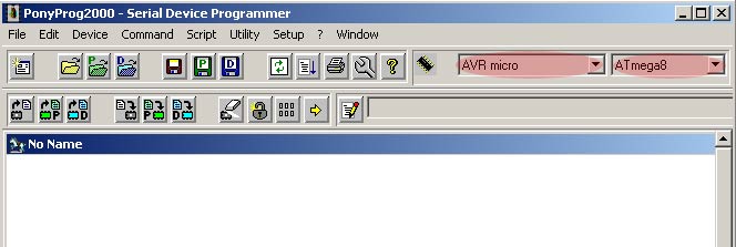
To be able to load hex files from your computer to the microcontroller, you will need to download and install the software. After installation, the first thing to do is to configure PonyProg to work with the AVR programmer. To do this, go to the “Setup” menu and select “Interface Setup”. The figure below highlights exactly the options you should select.

The next step is to select “AVR micro” and the type of microcontroller you want to program (for example ATmega8).
Now the PonyProg configuration is complete, and we can open the hex file with the program that will be hardcoded into the microcontroller. Go to the "File" menu, select "Open Program (FLASH) File..." and point to the hex file that needs to be flashed. You should see hexadecimal values similar to those shown in the image below. If you still haven't connected the programmer to your computer's serial port, now is the time to do it. Make sure that your programmer is physically connected to the AVR microcontroller via a socket board or a 6-pin ICSP connector. Finally, click on the highlighted “Write Program Memory (FLASH)” icon or go to the “Command” menu and select “Write Program (FLASH)”.
Click on the “Yes” button to confirm the entry.

Now sit back, relax and watch the programming process using the status indicator. PonyProg will flash the AVR microcontroller and check if the hex file was loaded without errors. This process usually takes between 10 and 30 seconds, depending on the size of the program you will be embedding into the microcontroller.
 |
 |
After programming, a “Write successful” window will appear indicating that the AVR microcontroller has been programmed and is now ready for use.

- Check installation and connection to the target microcontroller.
- Well, there’s nothing military in this circuit and there’s no need to make it, but I plugged in the Lonic’s com port into the computer and off I go, although I still have a buffer in my com port so that I don’t accidentally burn it. As for using the pony program, we forgot about one of the main things to say - about fuses, because if you install it incorrectly, the chip will get locked up
- com port is outdated. if there is only usb, then work with controllers can be considered finished without even starting???? No one on the network offers usb-com. And if they do, then there is a controller in the circuit. if you assemble it yourself, then from scratch. and not like many people do now, I ordered a designer, stuffed elements into the holes, soldered them, and that’s it. There are enough such geniuses in the service. and if you approach someone like that with a question, he doesn’t really know. but I want to know in detail.
- Well, of course, no one (spelled together!) offers. Since there are a lot of ready-made microcircuits in the typical inclusion - USB-COM bridges for 5V and 3.3V power supply. But very literate citizens naturally do not know about this. They also don’t know about the AVR910 analogue from Prottos, in which the MK via USB displays a virtual COM port and programs it via ISP. For example. The bourgeoisie also has a bunch of similar designs. And of course there are no detailed descriptions - you have to look for that. And you want something ready right away - you press one button and everything is on a silver platter. Or maybe it’s better to teach lessons?
- much respected SergeBS, this forum is not for spelling errors and especially not for teachings about what it is. here they ask for help and advice from people who know and have encountered this or that problem. but the fact that it’s ready-made and you can buy it without straining yourself is certainly cool. P.S. Nevertheless, thank you for your participation in the problem. AND A SPECIAL THANK YOU FOR THE VERY USEFUL TEACHINGS. Hello to the bourgeoisie, but I couldn’t even know what they have before? where do we go to peasants?
- Yes. Like the “cool” ones who write whatever they want. Moreover, they cannot even formulate the “problem”. Snot like: “I want to know the FAQ, but I don’t know the FAQ” - doesn’t count. :)
- You still don’t know what all this is made of... At a Chinese flea market, parts for your circuits are sold by weight in kilograms and no quality standards have anything to do with such parts. Buy only branded products from relevant companies.
- I order from online stores (Russian). Bye (ugh * 3) for defects/hackwork, etc. didn't fly.
- Hello! Happy New Year, everyone! :) I assembled a programmer for AVR according to the specified scheme (checked everything 3 times). But ponyprog 2000 refuses to see and program the ATMega168-20PU controller - it gives the error device missing or unknown device (-24). I used KS407G zener diodes, KT3102AM transistor and KD522B diode. I had quartz at 4.032 MHz. Powered by L7805. Before the error occurs, service messages arrive, which I monitor using the Advanced Serial Port Monitor, but they only turn Break on and off during the recording process. No data is lost. I set up PonyProg2000 according to the instructions. Step by step. What could be causing this error? Do I need to connect pin 22 to ground and pin 20 to power (analog ground and power)? Why is chip select not used (SS pin 16 of the controller)? Thanks for the help!
- I assembled this programmer and used: Resistors - the indicated values Transistor - KT3102GM Diode H48 is an analogue of 1N4148 Zener diodes - BZX55C 5.1 volts Also quartz at 4 MHz and 2 ceramic capacitors at 22 pF, but I don’t think that they are required because We set the use of internal/external quartz with programmable bits, from the factory the mikruhi are programmed to use internal quartz (if I’m not mistaken). External power from +5V is required. I connected it from the power supply of the same PC from which I uploaded the firmware. Diode H48 (this marking is not present on the body of this diode) on the Internet they say that this is an analogue of 1N4148. Everything works for me, PonyProg 2000 successfully uploaded the firmware to ATmega8. Photo http://i.imgur.com/34GhDcN.jpg http://i.imgur.com/gCzAuzA.jpg
- I would recommend one of the avr mk ii clone projects, based on lib and an example from lufa. The at90usb168 controller usually comes with a bootloader, which allows you to upload the firmware via USB after assembly without an external programmer. Supports all current avr, including xmega and new Tinki, pdi/tpi protocol. Works with avrstudio and dude, different firmware for them. The sources are open, the bugs have been worked out. For example, for new studios it is enough to increment the fw version in the firmware settings. The firmware is being compiled for winavr. My version in this topic, from 12 years old. With a photo. http://m.radiokot.ru/forum/viewtopic...rt=700&t=26417
- Hello. I assembled this programmer for ATtiny 2313 firmware, everything works. We read the MK without problems, but here is the problem. The author of the circuit for which I am flashing the MK wrote that for the first time you can flash it without an external quartz, but first upload the MK firmware, and then change Fuse In short, I uploaded the firmware, it installed fine, then I changed Fuse and clicked Write, but after I clicked Write this came out: Device missing or unknown device (-24) and after that the MK is no longer readable, what could be the problem?
- this is back, please tell me, I tried to flash ATtiny 2313 with external quartz and installed 2 capacitors, 8 MHz quartz, connector. program. he read the MK, opened the firmware in the pony, set Fuse, which ones are needed, these are the factory ones http://i.imgur.com/rSdlENN.jpg and these ones need to be flashed http://i.imgur.com/gc4yyxA.gif but what else I noticed in the factory settings there is one checkbox that cannot be removed called SPIEN, and which ones need to be flashed there is no this checkbox, ok, I’ll continue my problem after I opened the firmware and set Fuse as in the second picture, I clicked READ DEVICE, went through the firmware process and at the end this is what came out http://i.imgur.com/UpR5qhE.jpg then I closed the pony and opened it again and clicked read MK and got this Device missing or unknown device (-24) the same as what I flashed without external quartz, above described, and after that this MK was no longer read, who can tell me what’s wrong, what I did wrong. It’s just that I’ve already killed 3 MKs, thank you very much, I’m new to this
- I got this error only when I didn’t connect the external power supply, well, of course, you may have errors in the circuit, maybe you configured the pony prog for the wrong device (but it’s unlikely because I’m a newbie, I uploaded the firmware.) SPIEN is a fuse that allows it to work MK via SPI interface. All microcontrollers are released with the SPIEN bit already set. Considered a dangerous fuse...
- The SPIEN fuse bit is set by default in AVR microcontrollers (in-circuit programming mode) and cannot be removed using PonyProg. And in general it’s better not to touch it... Having installed and programmed the Fuse bits as in the last picture, you configured the microcontroller to operate from an external 8 MHz quartz, disabled the internal clock frequency divider by 8 and enabled the Brown-Out Detector (power control module) with a level of 2.7 V. And after that the programmer did not see the microcontroller, so it would be logical to supply external power to the microcontroller (not from PonyProg) and try to read it again. PS: Of course, if everything was done correctly initially (the type of microcontroller in the programmer was selected correctly during programming and the Fuse bits were set correctly)
- thanks for the answer, I just flashed the firmware for 3 MKs and now the program doesn’t see them and I need to change them, and I always supplied external power when flashing the firmware, but the pony still doesn’t see it, but the MK works, I inserted it into the device for whom I All three workers stitched it, but I need to upload others there. I asked the author of the circuit for which I was stitching them how to change them, he told me that if the external quartz is not detected, then you also need to make an external clock generator and send a signal to the XTAL 1 MK and then progrom. will see the MK if anyone can show a simple circuit diagram of an external clock generator, I googled a lot and didn’t find anything, or maybe someone else has a way, and Fuse, I definitely had to remember how in the second picture because it won’t work with the factory ones, thanks for the help
- Thank you for the article! Great adapter. It works quickly, without errors. First of all, I soldered the LPT port; I didn’t have a COM plug at hand. The LPT port burned out during the first fill. I had to run to the store to get a COM plug. I also recommend soldering the doctor's fuse - a very useful thing. I was the first to fuse the crystal so much, it seemed like it had released its soul (blue smoke), but nope! - Dokhdur fuse instantly brought him back to life. So it turns out: this adapter + dock fuse = a full-fledged parallel programmer.
- After the "blue haze" no doctor could bring him back to life. And “Doctor Fuse” - yes, it can probably be useful sometimes. But it is almost always possible to do without it, you just need to clock the MK not from quartz, but from an external generator...
- But I was lucky enough, at the very first configuration of the fuses, to slam it so that not a single generator could save it. I didn’t know that there are 2 options for displaying fuses: Direct (historical, canonical) and inverted (intuitively convenient). So I put in the canonical checkbox with the inverted photo. By the way, PonyProg operates with fuses in an inverted representation.
- Read for everyone: